background image


TOUCHPANEL CONFIGURATION 


System Setup 

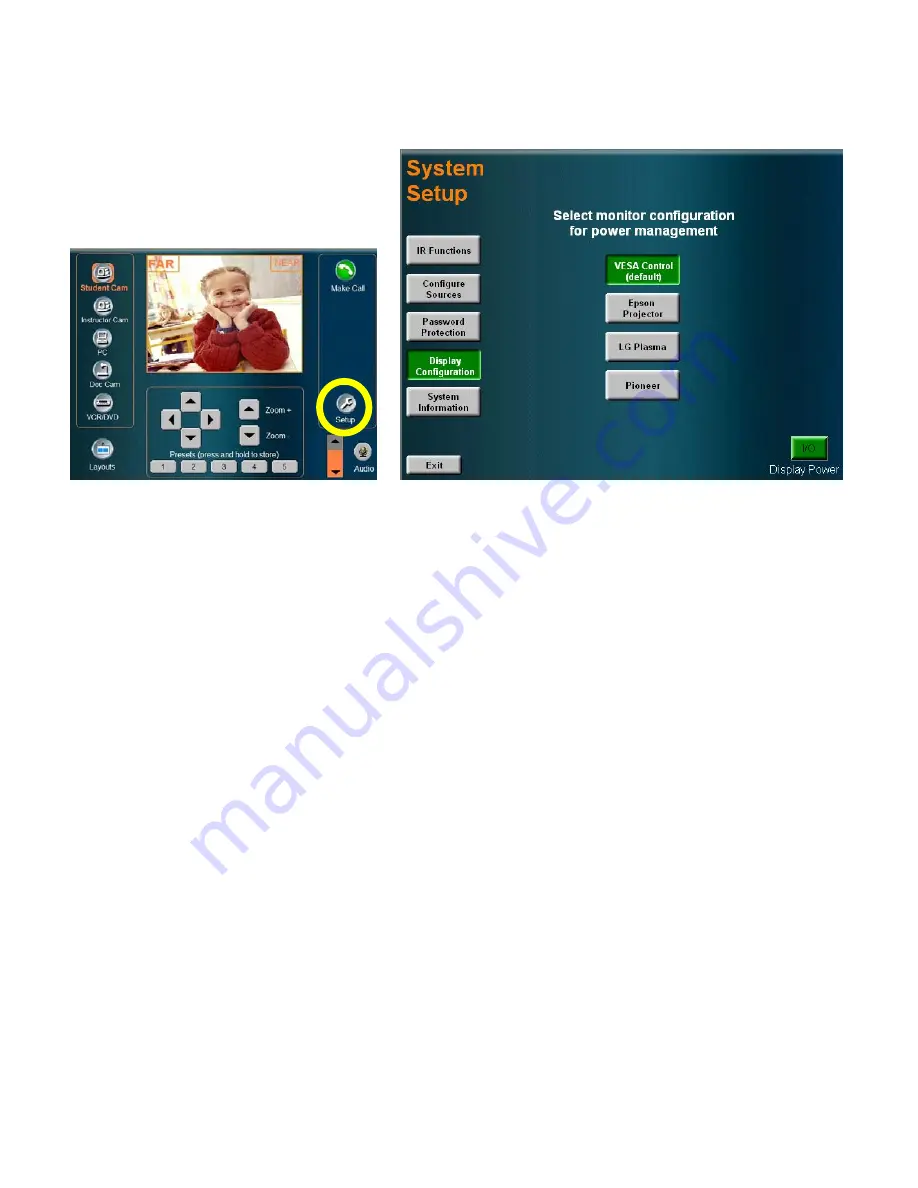
There are a number of setup options and 

configurations that can be utilized to customize 

and configure your system.  Press the SETUP 

button to enter the utilities and setup page. 


IR FUNCTION 

Presents a page for remote control emulation. 

CONFIGURE 

SOURCES 

Configure the peripheral devices that appear on the touch panel. 

PASSWORD 

PROTECTION 

Setup password protection for access to dialing, system, and setup pages. 

DISPLAY 

CONFIGURATION 

Configure display types to control. 

SYSTEM 

INFORMATION 

General system information. 

EXIT 

Exits setup page and returns to the MAIN page. 

DISPLAY POWER 

Powers down the display monitor(s) and puts the system/codec to sleep 


Page 22 of 32 

TANDBERG SCHOLAR ASSEMBLY, SETUP AND USER GUIDE  |  D50564.01 

Summary of Contents for Scholar MXP

Page 1: ...1 MARCH 2009 CODEC SOFTWARE V7 2 CONTROL SOFTWARE V2 2 TANDBERG Scholar MXP Assembly Setup User Guide This document is not to be reproduced in whole or in part without the permission in writing from T...

Page 2: ...ights of TANDBERG Portions of this document written by the Solutions Group of TANDBERG U S A and the Technical Support Department of TANDBERG Norway We are committed to maintaining a high level of qua...

Page 3: ...or third prong is provided for your safety If the provided plug does not fit into your outlet consult an electrician Power Cord Protection Route the power cord so as to avoid it being walked on or pi...

Page 4: ...THER COMPONENTS 19 TANDBERG SCHOLAR MXP SETUP GUIDE 20 SYSTEM CONFIGURATION CODEC TOUCH PANEL 20 CODEC CONFIGURATION 20 TOUCHPANEL CONFIGURATION 22 TOUCH PANEL OPERATION 25 MAIN PAGE 25 MAKING A CALL...

Page 5: ...ceiling optional Single Display Instructor Cart w PHD Camera optional The core components for the TANDBERG Scholar MXP system are Scholar MXP Equipment Rack TANDBERG 6000 MXP Codec 1U shelf w power s...

Page 6: ...2 long 1 2 OD mounting speaker bracket 4 10 32 x 5 pan head Phillips screw codec brackets 4 1 4 20 screw 2 5 pan head Phillips beauty panel 4 hinged screw cap for 1 4 20 screw beauty panel 4 8 32 x 1...

Page 7: ...MOUNTING BRACKET 2X DISPLAY BRACKET ADAPTER 4X SPEAKER BRACKET B 2X SPEAKER BRACKET A 2X HORIZONTAL U CHANNEL 2X VERTICAL SUPPORT POST 2X CART HANDLE 2X J HOOK CAPS 4X VESA MOUNT BRACKET 100MM OPTION...

Page 8: ...TOOLS REQUIRED 7 16 wrench or ratchet set 9 16 wrench or ratchet set 2 Phillips screwdriver Page 8 of 32 TANDBERG SCHOLAR ASSEMBLY SETUP AND USER GUIDE D50564 01...

Page 9: ...ing 4 Use 3 8 16 x 1 HEX BOLTS WASHERS 4 to secure the VERTICAL POSTS at the back of the cart 5 Mount the HORIZONTAL U CHANNELS 2 to the UPRIGHT SUPPORT POSTS using 3 8 16 x 2 HEX BOLTS and WASHERS 4...

Page 10: ...BOXES Leave the DISPLAY in the bottom packaging for the next step 10 Attach the DISPLAY MOUNTING BRACKETS 2 to the rear of the DISPLAYS using M8 x 16 BOLTS 4 When attaching the BRACKET to the NEC disp...

Page 11: ...0 LG 50PM1M 50 SMALL HOLE MOUNTING POINTS ON DISPLAY LARGE HOLE MOUNTING POINTS ON HORIZONTAL U CHANNEL SMALL HOLE MOUNTING POINTS ON DISPLAY LARGE HOLE MOUNTING POINTS ON HORIZONTAL U CHANNEL Page 11...

Page 12: ...PDP 607CMX 60 SMALL HOLE MOUNTING POINTS ON DISPLAY LARGE HOLE MOUNTING POINTS ON HORIZONTAL U CHANNEL SMALL HOLE MOUNTING POINTS ON DISPLAY LARGE HOLE MOUNTING POINTS ON HORIZONTAL U CHANNEL Page 12...

Page 13: ...CHANNEL 14 Attach ADHESIVE BACKED FOAM to the top front of SPEAKER BAR as shown and trim any excess foam 15 Attach SPEAKER BRACKETS B 2 to the SPEAKER BAR using the EXISITING SCREWS 4 16 Attach the S...

Page 14: ...OPTIONAL 100mm VESA MOUNT BRACKET 2 can be installed for mounting a VESA compatible PC or other peripheral device 23 Use the WIRING DIAGRAM on the following page to connect the appropriate cables and...

Page 15: ...CONTROL WIRING DIAGRAM Page 15 of 32 TANDBERG SCHOLAR ASSEMBLY SETUP AND USER GUIDE D50564 01...

Page 16: ...AUDIO WIRING DIAGRAM Page 16 of 32 TANDBERG SCHOLAR ASSEMBLY SETUP AND USER GUIDE D50564 01...

Page 17: ...VIDEO WIRING DIAGRAM Page 17 of 32 TANDBERG SCHOLAR ASSEMBLY SETUP AND USER GUIDE D50564 01...

Page 18: ...ar end and the decompression of the incoming information hence the name Codec compression and decompression Audio and Video Sources MAIN CAMERA AUX CAMERA The Main Camera is generally mounted on top o...

Page 19: ...rd will begin the recording Pressing stop on the lower controls will stop the recording See the peripheral wiring diagram for the Scholar MXP to ensure proper connections for recording PC LAPTOP COMPU...

Page 20: ...l is the primary source for presentation operation the remote is required for codec setup and menu navigation Video switching controlled by the remote control will not always function properly It is r...

Page 21: ...lso recommends setting Picture Layout to Picture outside Picture when using 16 9 monitors Picture outside Picture provides a display layout optimized for wide screen monitors The display layout may be...

Page 22: ...GURE SOURCES Configure the peripheral devices that appear on the touch panel PASSWORD PROTECTION Setup password protection for access to dialing system and setup pages DISPLAY CONFIGURATION Configure...

Page 23: ...is selected a submenu will appear to specify which video playback device is connected to the system that is to be controlled from the touch panel PASSWORD PROTECTION This selection provides three opti...

Page 24: ...y monitors that can be power managed by the system SYSTEM INFORMATION Pressing this will display general system information This information can be helpful when troubleshooting with TANDBERG Technical...

Page 25: ...Y WINDOW SOURCE CONTROLS MAIN SOURCE SELECTION VOLUME CONTROL MUTE CALL CONTROL LAYOUT OPTIONS VIDEO DISPLAY WINDOW This window will either display the currently selected video source or the received...

Page 26: ...DVD player or other A V source connected to the system The controls specific to the VCR DVD unit that is configured will appear in the SOURCE CONTROL area Any other A V source will not be controllable...

Page 27: ...ETUP to ADD EDIT or DELETE directory entries ADD Touch ADD to enter the name and call requirements for the new directory entry Press SAVE ENTRY to include this entry to the local directory EDIT Touch...

Page 28: ...MAIN SOURCE will display the content on the system s display STUDENT CAM Local view The camera controls appear in the SOURCE CONTROL area INSTRUCTOR CAM When a second camera is connected and configur...

Page 29: ...esired PRESENTATION source you wish to present The far end site will be able to see your selected source 4 Press PRESENTATION again to discontinue sending a presentation source This will not disconnec...

Page 30: ...000 MXP User Manual for more about MultiSite and MCU Services 1 While in a call press ADD SITE and select a directory entry or enter a number manually 2 Press CONNECT Repeat steps 1 and 2 if you would...

Page 31: ...ction correctly with the TAM MXP TANDBERG recommends rack mounting the TVS within 6 1 5m of the codec If you have the TANDBERG student cart there is 1U blank panel above the codec or on the 1U shelf T...

Page 32: ...een spilled or an object has fallen into the apparatus If the apparatus has been exposed to rain or moisture If the apparatus has been subject to excessive shock by being dropped If the apparatus does...

Reviews: