TANDBERG DIRECTOR D5016402 User Manual Download Page 94

Advanced Use

TANDBERG Director Videoconferencing System

94

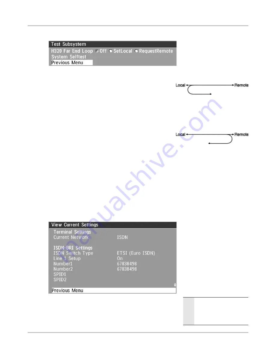
You can test the different
subsystems of your
videoconferencing equipment.

Far End Loop (ISDN only)

S

ET

L

OCAL

This system will loop all
incoming audio and video.

  - The far end will see its own

video and hear its own audio.

  - The local side will see and hear the far end.

An on-screen indicator will indicate ‘Local Loop’.

R

EQUEST

R

EMOTE

A request will be sent to set
the far end in loop.

  - The far end will see and hear

the local side (varies depend-
ing on implementation of loop functionality).

  - The local side will see its own video and hear its own audio (if the far

end supports loop).

If 

‘Far End Loop’

 is set to 

‘RequestRemote’

 while in a call and the call is subsequently

disconnected, ‘Far End Loop’ will be set to 

‘Off’

.

System Selftest

The system performs a check to determine internal hardware integrity. Test Network is useful when
you want to check if your network connection is active.

View Current Settings

This window will display all the
system settings. Use the arrow
key on the remote control to
scroll through the list.

Restore defaults

You may restore all system settings to the factory default using
this function.

N O T E

T

HIS


DEFAULT


SETTING


WILL


NOT

AFFECT


YOUR

 C

ALL

 D

IRECTORY

INFORMATION

, N

ETWORK

 T

YPE

,

L

INE

 S

ETUP


NUMBERS


OR


YOUR

SPID 

NUMBERS

Summary of Contents for DIRECTOR D5016402

Page 1: ...User Manual Director Software Version E1 B6 Control Software Version V3 0 D5016402 This document is not to be reproduced in whole or in part without permission in writing from...

Page 2: ......

Page 3: ...mmitment by TANDBERG The information in this document is believed to be accurate and reliable however TANDBERG assumes no responsibility or liability for any errors or inaccuracies that may appear in...

Page 4: ...nsure that they are not exposed to excessive vibration or shock If cabinet assembly is required we strongly recommend that at least two people perform this task Do not touch the rear surface of the in...

Page 5: ...ed on or pinched by items placed upon or against it Do not modify the power cord The socket outlet shall be installed near to the equipment and shall be easily accessible Never do any installation of...

Page 6: ...n 15 Installing the Guest Laptop Shelf 16 Installing the Adjustable Camera Shelf 17 Powering on the System 21 System Setup 21 SMART BoardTM Projector Setup and Calibration 21 Touch Panel Tools for Sys...

Page 7: ...4 Call quality 55 Presentations 57 Utilities 58 MCU services 60 Audio Settings 63 Video Settings 68 Terminal Settings 72 LAN Settings 81 Call Settings 87 Dataport configuration 90 Language 91 Software...

Page 8: ...ormation Design features 67 display with on screen touch controls Integrated mobile stand with electronic annotation markers and storage for multiple peripherals such as a PC and VCR W A V E II wide a...

Page 9: ...ra Adjustable Camera platform wireless keyboard laptop shelf Interactive touch SMART Board SMART pen tray speaker vent x 2 wireless keyboard holder lockable casters x4 key lock for door doors to mount...

Page 10: ...fer the REAR PROJECTION SMART BoardTM 3000i INSTALLATION GUIDE for more detailed description of features Touch Panel Control An optional 12 or 15 touch panel can be incorporated enabling a user to man...

Page 11: ...2 composite inputs available on the system Optional Equipment Additional Monitors An additional monitor can be added for viewing the far or local video Typically used to view the far side in a teachin...

Page 12: ...olution 15 pin female HD D sub connector 4 AUX CTRL 1 Bi directional RS232 9600 N 8 1 9 pin female D sub connector 5 AUX CTRL 2 Bi directional RS232 9600 N 8 1 supports SMART BoardTM 3000i Room Contro...

Page 13: ...Introduction TANDBERG Director Videoconferencing System 13 Rear Interface Panel Connections...

Page 14: ...Introduction TANDBERG Director Videoconferencing System 14 Rear Interface Panel A V Plate...

Page 15: ...ION CONSIDERATIONS for more information Installation Setup Room Configuration The TANDBERG Director system has been designed to provide versatility for installation at any site whether for corporate m...

Page 16: ...s on the edge of the shelf into the two keyholes and then push the shelf firmly down 3 Push the captive thumbscrew at the bottom of the shelf into the thumbscrew hole and tighten TIP YOU CAN INSTALL T...

Page 17: ...E OF THE CABINET THE MOUNTING ARM OF THE SHELF PROVIDES A CONVENIENT HIDDEN CHANNEL FOR THE CAMERA CABLING To install the videoconferencing shelf 1 Choose the side on which you want to mount the shelf...

Page 18: ...ough the large hole down the channel and through the lower mounting point 3 If you re installing the mounting arm on the same side as the IR receiver detach the receiver and leave it temporarily dangl...

Page 19: ...place of the 1 4 20 x fasteners removed in step 1 to secure the mounting arm to the cabinet The safety screw is now replaced 5 Hook the shelf to the keyholes in the mounting arm tightening the thumbsc...

Page 20: ...it to reattach it to the bottom of the mounting arm 8 To connect the camera to the system find the cable loom cable S061 that has three corresponding connectors for the camera the cable should be coil...

Page 21: ...utton on the front of the 3000i cabinet Once powered refer to SYSTEM SETUP for screen calibration RED YELLOW GREEN N O T E IT IS RECOMMENDED THAT YOU PRESS THE GREEN PROJECTOR STANDBY BUTTON TO PLACE...

Page 22: ...evice used to calibrate the screens Carefully touch the calibration points and after the third point the system will restart and return to the opening start up page In rare cases it may not be possibl...

Page 23: ...tion IR functions audio system options and directory information can be accessed and edited System Information This button gives information about options and bandwidths available on the codec The Dir...

Page 24: ...ote See GETTING STARTED TOUCHSCREEN AND REMOTE IR CONTROLS Audio Choosing the AUDIO button will display the audio inputs and outputs of the codec Touching the or for each input will raise or lower the...

Page 25: ...new directory entry or select an existing directory entry to edit that information Refer to VIDEOCONFERENCE OPERATION EDITING SPEED DIAL DIRECTORY for more information Update Directory Click UPDATE DI...

Page 26: ...1 on the codec Connect the other end of the cable to a Channel Service Unit CSU Then connect the CSU to the site s PRI T1 line Other Networks Using the External Network Interface If you are using oth...

Page 27: ...ource selection corresponds to the first s video input labeled 1 on the codec This camera input used specifically with the controllable TANDBERG W A V E II camera AUX Camera The auxiliary camera sourc...

Page 28: ...ard and mouse cables are locat ed nearby Make the appropriate connections to the PC Laptop You may choose to connect a laptop computer to the 3000i as a source for presentation This can be done in con...

Page 29: ...RT Board Software select the PC as your video source and use the Orient utility found in the SMART BoardTM Software s Control Panel You can also calibrate the PC software by holding down the KEYBOARD...

Page 30: ...configured from the left side Selecting the right hand side will display the source selection and device control on that right side of the screen The taskbar controls will be configured from the righ...

Page 31: ...STEM S CAPABILITIES IR Functions The system s most commonly used functions can be accessed directly from either the touch screen or remote IR control with single key presses The IR controls are partic...

Page 32: ...Controls will appear in the place of the Address Book Pressing the TANDBERG LOGO again will toggle between the Address Book and IR Controls Using the IR Controls you can navigate the codec s menu str...

Page 33: ...Switch Type Channel Hunting Line Settings Adv PRI Settings Terminate Meeting Disconnect Site Release Floor to Site Floor to Site Release Chair Take Chair Chair Control End View View Site Terminal Nam...

Page 34: ...ystem Name to identify the system during an MCU conference Select Utilities System Name Enter the name using the NUMBER KEYS as on a mobile phone Select the language you want to use in Terminal Settin...

Page 35: ...cify the settings for the selected network in one of the menus For details follow the instructions in TERMINAL SETTINGS NETWORK CONFIGURATION in this manual For further information refer to the exampl...

Page 36: ...set up to utilize the DuoVideoTF feature however it requires that the far end videoconferencing system is DuoVideoTF enabled When DuoVideoTF operation is possible a DUOVIDEO button will be present on...

Page 37: ...umber is found in the directory the calling party s name will be displayed instead of the number on the status line See VIDEOCONFERENCE OPERATION EDITING SPEED DAIL DIRECTORY for adding and editing di...

Page 38: ...minute reversible period Press and hold the PROJECTOR STANDBY button for a few seconds until you see Please Wait a Moment appear on the bottom of the screen Release the button and the lamp starts pow...

Page 39: ...MultiSiteTF Both ISDN IP and mixed ISDN IP conferences can be encrypted if all systems supports encryption For encrypted calls there is a maximum bandwidth of 768 Kbps for the whole conference This m...

Page 40: ...audio site each These systems will automatically run Voice Switched mode and transmit a full screen image to the host when calling on ISDN When calling on IP Voice Switched Mode must be selected manua...

Page 41: ...n the window displayed When selecting Send Text the text will be displayed on the local and far end monitor as shown below The local Text Chat window can be closed manually from the Web interface by p...

Page 42: ...456 1234567890123456 1234567890123456 1234567890123456 1234567890123456 1234567890123456 1234567890123456 LocalVideo Camera Control Video Sources TaskBar Display Operation Local Display Operation When...

Page 43: ...ted it can be controlled See DEVICE CONTROL Sends the Document camera to the video display No device control are available for this source Sends the VCR or DVD to the video display No device control a...

Page 44: ...E MICROSOFT WINDOWS MACINTOSH HIDE removes the taskbar from the screen a single Taskbar button replaces it TASKBAR displays the taskbar on the bottom of the screen EXIT from the local display operati...

Page 45: ...be displayed in the white text bar You can use the UP DOWN ARROWS to scroll or page through all the available speed dials 2 If this is the site you wish to call press the green CONNECT button The call...

Page 46: ...site is not answering select the red HANG UP button to disconnect the call 6 When the call is established the Videoconference Main Screen will be displayed On the Manual Dial screen the following con...

Page 47: ...up 2 Select ADD NEW ENTRY 3 Selecting the white text boxes will allow you to enter the name and phone number s within that field The currently selected field will be circled in red The CALL QUALITY c...

Page 48: ...select the CALL CONTROL button on the TASKBAR 2 From the Address Book Screen follow the previously described procedure to either select a Speed Dial 3 Press the green CONNECT button The call will be...

Page 49: ...f the device has no associated controls this area will be blank SOURCE SELECTION allows the available video sources to be selected TASKBAR is where the functions relevant to the current system operati...

Page 50: ...g Disables sound from all microphones within the room While the mute is active the button border and text is blinking red and an on screen mic off icon appears De activate by pressing Mic Mute again T...

Page 51: ...f the far end site is configured for far end camera control the camera control and source selection will change to red indicating that FAR END CONTROL is selected The available far end sources will al...

Page 52: ...ocal display monitor of the remote system this image is usually the content being presented the document or PC source The DEVICE CONTROLS that appear function for the Duo source only It is still possi...

Page 53: ...Sites or terminate the meeting Select this button then the site that will be viewed by all other participants This function requires Chairman control Select this button then the site name and that sit...

Page 54: ...y Menu Password It is possible to password protect the menus on the TANDBERG system To activate this feature specify a Menu Password in the Utilities menu By doing this only dialing and camera control...

Page 55: ...laced video capabilities iCIF will be transmitted and enabled When set to AUTO Natural VideoTF will be transmitted from 768Kbps OFF Interlaced capabilities will not be transmitted This is useful if fa...

Page 56: ...tural VideoTF 352 x 576 pixels for PAL 352x480 pixels for NTSC only for H 263 CIF High resolution video 352 x 288 pixels QCIF Low resolution video 176 x 144 pixels H 331 OFF Standard two way communica...

Page 57: ...be simultaneously transmitted to the far end SHARPNESS DuoVideoTF is optimized for sharp video Digital ClarityTF This mode is ideal when using a document camera or a PC on DuoVideoTF If the far end d...

Page 58: ...snapshot Snapshot Filter Select On to remove any instability in the high quality snapshot Utilities Autoanswer ON The system will automatically answer all incoming calls ON MICOFF The system will aut...

Page 59: ...ive site will be displayed in full screen during a MultiSiteTF conference Also called Voice Switched mode MCU status line ON The MultiSiteTF MCU DuoVideoTF indicators will be displayed and provide inf...

Page 60: ...described below Quick Menu When connected to an MCU This menu provides access to the most commonly used MCU functions If Request Floor is selected Request Floor will change to Release Floor If View S...

Page 61: ...r the chairman decides to release the floor to another participant Release floor You choose Release Floor to take you Off Air You should do this when you wish to make the floor available to the other...

Page 62: ...you the chair Release chair Allows you to relinquish the privileges of chairmanship of the conference Floor to site Allows the chairman to select which of the conference participants is to be broadca...

Page 63: ...or connection to external playback devices or to telephone add on hybrids As there is no acoustic echo canceller on this input it should not be connected to any microphones The audio entering this inp...

Page 64: ...t input level settings The input level should be adjusted so that the average level reaches the preferred level marker The audio inputs are adjustable in steps of 1 5 dB from 0 dB to 22 5 dB The defau...

Page 65: ...ing equipment or to a telephone add on hybrid The signal is a mix of audio from both the far end and local end not from Audio in 5 Adjust the audio output levels according to the parameters of the ext...

Page 66: ...d noise e g noise from air conditioning systems cooling fans etc In addition a highpass filter Humfilter reduces very low frequency noise Choose On NR to activate both Echo Control and Noise Reduction...

Page 67: ...e ratio distance loudspeaker to mic mic to speaker can be increased Increasing this ratio improves the echo canceller performance Avoid distances above two meters from any participant to his her close...

Page 68: ...many audio settings It is easy for the user to configure the codec to be unusable Therefore it is possible to return all audio settings to their factory default settings by using Restore Audio Defaul...

Page 69: ...should be activated when pressing PC VGA Pressing PC will activate the VGA input on the system default VNC Pressing PC will use VNC to show images from your PC see VNC Settings for further informatio...

Page 70: ...A Out connector at the rear of the codec AUTO Will sense the resolution on the VGA input port and use the same resolution on the VGA Out port VGA Will force VGA out to VGA 640X480 SVGA Will force VGA...

Page 71: ...asterisk signs the next time you enter the menu Start using VNC To activate VNC press PC on the remote control Please make sure that PC is set to VNC in the Video Settings Menu See also PC SOFTPRESENT...

Page 72: ...want to use your system via ISDN PRI you should select Current Network ISDN PRI and enter the ISDN PRI Settings menu to set the PRI parameters If you want to use your system via Leased E1 T1 you shou...

Page 73: ...RK PROPERLY USING ISDN BRI MAKE THE FOLLOWING SETTINGS SET ISDN SWITCH TYPE ENTER ISDN LINE NUMBERS SPIDS IF REQUIRED DISABLE UNUSED LINES N O T E IF NATIONAL ISDN IS SELECTED PRESS THE QUICK KEY AUTO...

Page 74: ...always be enabled National ISDN and AT T Custom ISDN might require SPID numbers associated with your ISDN numbers If you have received two different SPID numbers for each ISDN line from your telephone...

Page 75: ...ers to the far end but please note that the network may still send your numbers to the far end Sending Complete ON The system will send the ISDN message information element Sending Complete OFF The sy...

Page 76: ...f only TANDBERG units are used in the daisy chain default setting should be used as these units will find available B channels automatically Max Channels may be used for PRIs that are provisioned for...

Page 77: ...port on codec 2 Possible values are 0 115 feet 80 215 feet 180 310 feet 280 410 feet 375 510 feet 475 605 feet 575 690 feet E1 CRC 4 is used for most E1 PRI configurations You can turn it off if not...

Page 78: ...dicates if the network is of type E1 30 channels or T1 24 channels E1 will be default for PAL versions T1 default for NTSC versions Max Channels Indicates the maximum number of channels the codec is a...

Page 79: ...the handshaking signals DTR and CD are available DTR and CD correspond to the X 21 network s C and I signals Data Triggered mode uses TxData transmit data RxData receive data and clock signals only Us...

Page 80: ...both transmit and receive Cable Specification V 35 V 35 RS 366 cable Signal Name Female Male 34pin Male 25pin Comments 26pin DSUB Winchester DSUB Pin number Pin number Frame ground 1 A Signal ground...

Page 81: ...client to know which stream to receive If the first codec streams on port 2240 and the second codec on port 2250 the client has to specify which port to listen to Video is transmitted on the specified...

Page 82: ...e codec s streaming session Used by Cisco IP TV OFF No announcement packets will be transmitted Video Rate Defines the Video streaming rate from the system Range is 16kbps 320kbps In addition audio G...

Page 83: ...he codec within 30 seconds this specific gatekeeper will be used If no gatekeeper responds the codec will not use a gatekeeper for making H 323 calls and hence an IP address must be specified manually...

Page 84: ...encing system when the IP traffic goes through an NAT router When NAT is On the NAT Server Address will be shown in the startup menu My IP Address 10 0 2 1 NAT NAT Address This must be the external gl...

Page 85: ...Audio Video Data and Signaling packets should have in an IP network The priority ranges from 0 to 63 for each type of packets IP Type of Service TOS Helps a router select a routing path when multiple...

Page 86: ...used in static mode Your LAN administrator will provide the correct value for this field Gateway When using DHCP the default gateway will be set automatically If the LAN utilizes static IP addresses I...

Page 87: ...manager Traps can be sent to multiple SNMP Trap Hosts Enter the IP address of up to three SNMP managers All traps will then be sent to the hosts listed SNMP Community SNMP Community names are used to...

Page 88: ...d without encryption MultiSiteTF calls In order to have encrypted MultiSiteTF calls all sites must support encryption The padlock symbol will indicate encryption mode AES or DES If there is a mix of A...

Page 89: ...pabilities of the other sites If AES encryption is not supported by all the other sites DES encryption will be tried AES The system will try to use AES with 128 bits encryption when setting up calls I...

Page 90: ...control interface provided by the Dataport supports a subset of the Hayes command set as well as a comprehensive set of system specific commands This mode maintains communication with the Dataport s...

Page 91: ...oftware Options All Director systems have Security contains Secure Conference AES Natural Presenter PackageTF and MultiSiteTF options enabled All TANDBERG systems require a valid option key to activat...

Page 92: ...ss is available through the Channel Status window This window indicates the various stages each B channel goes through whilst establishing a connection Status BRI C o m m e n t s Idle the channel is i...

Page 93: ...hand side of the window TIP PRESS MENU AND THEN CALL STATUS TO BRING THIS MENU UP WHEN NOT IN THE MENU SYSTEM 1 Unallocated unassigned number 2 No route to specified transit network WAN 16 Normal clea...

Page 94: ...side will see its own video and hear its own audio if the far end supports loop If Far End Loop is set to RequestRemote while in a call and the call is subsequently disconnected Far End Loop will be...

Page 95: ...ting the system to ISDN using NT1 network adapters Appendix 2 Connecting the system to the Switched 56 network Appendix 3 Connecting the system to PRI T1 Appendix 4 Environmental considerations Append...

Page 96: ...rovided from your network provider TANDBERG can provide NT adapters For convenience the NT1 adapters could be placed inside the cabinet If needed use the shorter ISDN cable RJ45 connectors delivered w...

Page 97: ...figuration of the Telesync Adapter is necessary Configuration of the system Select network type to National ISDN Set Restrict 56k Circuit 1 Circuit 2 SW56 Line 1 Line 2 BRI S T TANDBERG Telesync Adapt...

Page 98: ...ect the second Codec to the E1 T1 port 2 on the first Codec using a T1 crossover cable Configuration of the system Press MENU on the remote control Select Terminal Settings Network Select Current Netw...

Page 99: ...vered with curtains or sound treatment AUDIO Noise Floor Maximum 50dBC Noise Floor preferred less than 44dBC Reverb Time 3 to 5 sec Absorption Coefficient 25 to 45 No flutter echoes VENTILATION Keep i...

Page 100: ...s menu If a subject is backlit e g a person in front of a window it will appear dark This can be corrected by switching on the backlight function automatic on some cameras Dim scenes can also be impro...

Page 101: ...nd TANDBERG system B3 or above via ISDN upload of custom logos Software upgrade Connect to the system you want to upgrade using ISDN Copy the software file to a folder on your harddisk Open a DOS wind...

Page 102: ...e is located Type ftp IP address of your local codec User press Enter or enter IP password Type bin and press Enter Go to the user folder type cd user Upload the access txt file type put access txt Ex...

Page 103: ...e TANDBERG systems is fully automatic and provides clear security status indicators An open padlock indicates that encryption is being initialized but the conference is not yet encrypted Single padloc...

Page 104: ...are similar between both control interfaces Please refer to the appropriate section in this manual for detailed information Local Display Operation When the system is not in a videoconference call th...

Page 105: ...participant Moves and zooms either the Main or Aux camera to a predefined room view To Store a preset Move the camera to the view required Press and hold the PRESET button you want to sent until the...

Page 106: ...enlarge certain video display windows by simply touching the video window itself Touching the window again will return it to the previous size N O T E TASKBAR REFERENCES ARE FOR THE TANDBERG INTERFACE...

Page 107: ...led information When the Director receives initiates a video audio call When an incoming call connects the user will be automatically taken to the Videoconference Main Screen otherwise on the TASKBAR...

Page 108: ...the same as the LOCAL DISPLAY OPERATION screen VIDEO DISPLAYS shows both the LOCAL VIDEO source and the REMOTE SITE DEVICE CONTROL presents controls specific the chosen video source will be displayed...

Page 109: ...ew Touching the screen again will return you to the last arrangement of conference screens Displays the PC contents as a local preview only in a large screen with the remote and sending sources in sma...

Page 110: ...UDIO INPUTS 6 INPUTS 1 x Director mic 24V phantom powered XLR connector 1 x additional AudioScience mic 24V phantom powered XLR connector 1 x additional Table Top mic 24V phantom powered XLR connector...

Page 111: ...password Possibility to disable IP services NETWORK INTERFACES 6 x ISDN BRI RJ 45 S interface 1 x E1 T1 G 703 RJ 45 for ISDN PRI or leased E1 T1 1 x E1 T1 RJ 45 for ISDN PRI cascading 1 x LAN RJ 45 10...

Page 112: ...ation Protocol RTS Ready To Send DSU Data Service Unit SIF Source Input Format DTR Data Transfer Rate SNMP Simple Network Management Protocol DTX Discontinuous Transmission SPID Service Provider IDent...

Page 113: ...odec basics 33 Codec configuration 34 Confidence display 48 49 Connect 45 48 Continuous presence 52 59 60 61 110 Control 90 Control interface 10 Control orientation 30 Control panel 21 Copyright 3 Cre...

Page 114: ...27 63 67 AudioScience mic 10 110 Director microphone 110 Mic levels 64 muted turned off 49 Table top microphone 10 110 Microsoft Netmeeting 110 Mix mode See Audio Mobile stand 8 Modem 90 Monitor size...

Page 115: ...110 Telephone 65 110 Televisions 65 TerminaI settings ISDN BRI 73 Terminal names 61 Terminal program 22 Terminal settings 35 72 Advanced ISDN settings 74 ISDN switch type 73 ISDN BRI 72 ISDN PRI setti...

Page 116: ...ure If the apparatus has been subject to excessive shock by being dropped If the apparatus does not operate normally when following the operating instructions Note TANDBERG will provide on request cir...

Reviews: