CHAPTER 5: Using Your Tape Drive
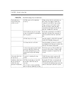
Table 5-3.
Front Panel LED/Control Functionality
LED/Button
Symbol
LED Color
Description
Write Protect LED
(Left on SDLT 220)
OR
Drive Density LED
(Left on SDLT 320)
Amber
For the SDLT 320 drive, this LED functions as the
“Drive Density Indicator” LED; for the SDLT 220
drive, this LED is the “Write Protect” LED.
ON
220:
Tape is Write-Protected
320:
Tape is 220-Formatted
OFF
220:
Tape is Write-Enabled
320:
Tape is 320-Formatted
Drive Status LED
(Center)
Green
Blinking: The drive is in use; this includes functions
such as:
•
the tape is moving
•
the drive is calibrating, reading, writing, or
rewinding the tape
•
the tape is loading, unloading or rewinding.
ON: The drive is idle. There may or may not be a
cartridge in the tape drive.
OFF: There is no Off state.
Cleaning Required
(Right)
Yellow
Cleaning Required. See
“Cleaning the Tape
Mechanism” on page 5-7
.
Eject Button
Use the Eject button to eject the tape cartridge from the
drive. When you press the button, the drive completes
any active writing of data to the tape, then ejects the
cartridge.
Refer to the applicable tape cartridge appendix for
detailed tape cartridge handling procedures.
Infrared
Communication
Port
This infrared port, also known as the Global Storage
Link (GS Link), provides a wireless remote testing
base for customers and integrators to access system
diagnostic information. See your Quantum sales
representative for more information.
220
Summary of Contents for SDLT220-320 INTEGRATION
Page 1: ...TANDBERG Super DLTTM Product manual Revision 2 June 2002 432589 01...
Page 20: ...CHAPTER 1 Introduction...
Page 34: ...CHAPTER 2 SDLT 220 320 Product Information...
Page 52: ...CHAPTER 3 Drive Specifications...
Page 76: ...CHAPTER 4 Installing Your Tape Drive...
Page 92: ...CHAPTER 5 Using Your Tape Drive...
Page 104: ...CHAPTER 6 SCSI Description...
Page 120: ...APPENDIX A SDLT I Tape Cartridge...
Page 130: ...APPENDIX B DLT IV Tape Cartridge...


