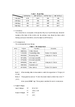
Table 1 Baud Rate
DIP SW No.1
DIP SW No.2
DIP SW No.3
DIP SW No.4
1200 bps
OFF
OFF
ON
ON
2400
bps
OFF ON OFF ON
4800 bps
ON
OFF
OFF
OFF
9600
bps
ON OFF ON OFF
(3)
Connection
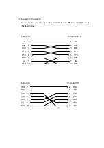
The connection to a computer is through the 25 pin or 9 pin D-Sub type connector
located at the back of the control unit. An extreme care should be taken when
making pin-to-pin connections, since the tester is a DTE device.
(4)
Pin Assignment
The pin assignment is as follows:
Table 2 Pin Assignment
Pin #
Signal
Function
Direction
1
GND (FG)
Frame Ground
2 TXD
(SD)
Transmitting
Data Tester
Æ
Computer
3
RXD (RD)
Receiving Data
Computer
Æ
Tester
4
RTS (RS)
(Connect w/pin #5)
5
CTS (CS)
(Connect w/pin #4)
6
DSR (DR)
(See note-1)
Computer
Æ
Tester
7
GND (SG)
Signal Ground
20
DTR (ER)
(See note-2)
Tester
Æ
Computer
Note-1: When starting data communication, switch this signal line to “0” logic (3V
to 12V).
Note-2: This signal line turns to “0” when the tester detects a flash; then turns “1”
(-12V)
when press RESET key. This signal is provided for user’s convenience.
(5)
Signal Voltages
Input Voltages
“0”:
3V to 12V
“1”:
-3V
to
–12V
Output Voltages “0”:
12V
“1”:
-12V

