


VOIP-500 Series Quick Installation Guide
Copyright 2010 Talk-A-Phone Co. All rights reserved.
Talk-A-Phone Co.
• 7530 North Natchez Avenue • Niles, Illinois 60714-3804
Page 2 of 6
Phone 773.539.1100 • Fax 773.539.1241 • [email protected] • www.talkaphone.com
All prices and specifications are subject to change without notice.
Talk-A-Phone, Talk-A-Lert, Scream Alert and WEBS are registered trademarks of Talk-A-Phone Co.
III. Field Wiring Installation
1. Remove and set aside the
VOIP-500 Series Emergency Phone
Assembly.
2. Remove the back box from the
VOIP-500 Series Emergency Phone
Assembly by
unfastening the six (6), #6-32 nuts and washers.
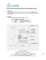
3. For PCB (Printed Circuit Board) wiring details, refer to
Figure 2.
Figure 2. Internal PCB (Printed Circuit Board) view
IV. Power
Power over Ethernet (PoE)
1.
Connect the Network (Ethernet) cable to the “WAN Ethernet” port on the PCB, as shown
in
Figure 2
. Nominal draw of the phone in PoE mode is 150mA (+36-57 VDC).
2. When installing the Network cable, it is essential to have a ferrite core provided with the
phone, installed on to the cable as close as possible to the phone. Make sure, the
network cable is passed twice through the ferrite core, forming a loop of not less than one
(1) inch in diameter.
A Cat5e or higher cable with RJ45 connector is typical for all network cables.


