Talis ERHARD HALIOSTM Installation, Operation And Maintenance Manual Download Page 15

P15

/19  

IOM_FIH210201_HALIOS STD-PREM_EN

The technical data and performance may be modified 

without prior notice depending on the technical advances.

Our underground fire hydrants are maintenance free. 
However, the complete bonnet, the operating inside trim, and 
the complete outlet claw (including foreign matter deflector 
and cap) can be removed and installed from the road through 
the street cap (see section 7.4 for composition of spare parts 
set). In the event that it is necessary to replace any part of 
the hydrant, follow the instructions below. Replacement of the 
shut-off ball, inlet flange gasket or drain tube can be done only 
if the hydrant is totally disassembled from the water network.

 7.3  Replacement

WARNING

Before carrying out inspection or any repair work on the 

hydrant, the pipe section in which the hydrant is installed 

must be depressurized and safe, e.g. by closing the gate 

valve and emptying. A built-in double shut-off and / or 

closed gate valve installed upstream of the hydrant are 

no guarantee that the hydrant inside is depressurized.
After maintenance works, when putting back under 

pressure, it is essential to operate the hydrant very 

slowly when opening because some air under pressure 

might have become trapped.

16

27

8.4

8.1

7

13

10

25

26

2

5

3

6

12

1

15

18

17

13

12

20

21

19

14

11

8.3

8.2

9

4.2

4.1

22

23.1

23.2

24.1

24.2

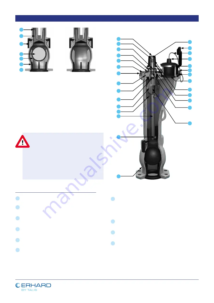
Double shut-off (UHAD)

Single shut-off (UHA)

7.3.1  Replacement of the complete bonnet: 

1

 Isolate the network section where the hydrant is installed 

(upstream). 

2

 Depressurize the network section where the hydrant is 

installed. 

3

 The hydrant should be fully closed by turning the square 

cap (14) clockwise.

4

 Completely unscrew the hexagonal bolts (13) of the bonnet 

(7).

5

 Turn the square cap (14) anti-clockwise until the operating 

stem (9) is out of the operating nut (2).

6

 Remove the complete bonnet (7) including the bonnet 

O-ring (10). 

7

 Replace the complete bonnet by a new one (7) including 

a new bonnet O-ring (10). Before installation, lubricate the 

operating stem (9) and wedge nut (2) and bonnet O-ring 

(10) with a small amount of appropriate grease (see in the 

paragraph 7.1).

8

 Re-assemble the complete bonnet (7), repeating these 

operations in reverse order.

9

 Make a full opening and closing of the hydrant without 

pressure.

10

 Check the correct operation of the product under pressure.  

When opening, be careful of the release of air that might have 

become trapped under pressure.

Summary of Contents for ERHARD HALIOSTM

Page 1: ...l description 3 Transport handling and lifting 4 Storage 5 Installation into the pipeline 6 Commissioning and Operation 7 Maintenance 8 Hydraulic characteristics 9 CE marking 10 After sales service co...

Page 2: ...cidents applicable in the user s country and place of installation the approved technical rules for relevant worker qualifications and safety standards must also be adhered to The user s staff are res...

Page 3: ...energy compressed air pressurized water hydraulic system must be avoided A copy of the operating and maintenance instructions must always be available on site and must be protected against oil and gre...

Page 4: ...that are specific to the country Safety regulations for hydraulic hose pipes European Construction Products Directive 89 106 CEE DVGW worksheet W331 1 2 10 Dangers caused by electric energy A potentia...

Page 5: ...alled component can withstand for a relatively short time not valid for non closed valves Each product is individually tested on the production line before delivery The strength and tightness of the g...

Page 6: ...let claw and bonnet 4 A2 70 A2 70 14 Operating square cap 1 EN GJS 450 10 3 EN GJS 450 10 3 15 Bolt 1 A2 70 A2 70 16 Square cap plug 1 PE HD PE HD 17 Foreign matter deflector 1 EPDM EPDM 18 Outlet cla...

Page 7: ...ises through the vertical tubing 7 to emerge at the outlet claw 11 During the downward movement of the shut off cone 4 its two guiding lugs close the two drainage orifices 3 The rotary motion in the c...

Page 8: ...5 80 UHA 1 25 922 48 243 178 120 108 75 50 110 9 4 30 5 80 UHA 1 50 1172 48 243 178 120 108 75 50 110 9 4 34 5 80 UHAD 0 75 474 48 243 178 120 108 75 50 110 9 4 24 80 UHAD 1 00 672 48 243 178 120 108...

Page 9: ...a flow restricting position can cause cavitation and major wear of the products that will lead to leakage and malfunctions This type of underground fire hydrants is suitable only for OPEN CLOSED opera...

Page 10: ...operations Hydrants too heavy to be handled manually must be transported by means of a lifting device suitable for the weight involved e g broad belts Avoid use of chains and ropes in order to protec...

Page 11: ...iguration of the material in order to control the compatibility of the hydrant with the fluid that is going to flow inside and with the external environment By turning the operating square cap anti cl...

Page 12: ...stalled it must be subject to a visual check After installation the hydrant must be checked for movement of the inner valve turn the square cap over the total stroke OPEN CLOSE Each hydrant must be op...

Page 13: ...high flow velocity An extension of the operating key by use of a lever or similar is not allowed It is not permitted to open the hydrant against a closed inspection or revision valve Do not exceed op...

Page 14: ...mplete Bonnet The hydrant is not opening Upstream isolating valve is closed Check the opening or open the upstream isolating valve and try again to close the hydrant Defective operating nut Replace op...

Page 15: ...er pressure it is essential to operate the hydrant very slowly when opening because some air under pressure might have become trapped 16 27 8 4 8 1 7 13 10 25 26 2 5 3 6 12 1 15 18 17 13 12 20 21 19 1...

Page 16: ...round 30 mm Align the holes of the bonnet with the threaded holes of the body Place two special hexagonal bolts M16 of minimum 70 mm length with their washers M16 and screw them gradually in alternate...

Page 17: ...0 SPA00071TS Operating inside trim RD1 50 EPDM cone HALIOSTM 2 3 4 5 6 10 SPA00073TS Complete flange bearing HALIOSTM HALIOSTM Premium 7 8 1 8 2 8 3 8 4 9 10 11 both colors 12 13 14 15 16 25 26 27 SPA...

Page 18: ...he object of a CE marking and also a CE declaration of conformity 10 AFTER SALES SERVICE CONTACT For technical assistance or all questions that concerns the product or IOM manual please find the detai...

Page 19: ...nnovative technology global expertise and individual consultation processes form the basis for developing long term solutions for the efficient treatment of the vitally important resource water ERHARD...

Reviews: