background image


-


24


-


3.


Relating Conditions with Programs 


Conditions  can  be  used  for  causing  programs  to 

start/  stop

  or  for 

enabling  / 

disabling

 their operation.  


In  this  chapter  we  shall  explain  how  conditions  can  be  related  with  irrigation 

programs,  however  prior  to  using  the  conditions  they  must  first  be  defined. 

Conditions definition is done at the 

CONDITIONS LIBRARY

 (see below). 


The 

CONDITIONS LIBRARY

 can be reached through the               submenu, or by 

the shortcut 

F3 = "Cond" 

that is revealed when


the cursor is located at the column 

of conditions number. 


By specifying the ordinal number of the desired condition in the row of the desired 

action  we  create  a  relation  that  will  cause  the  action  to  be  executed  when  the 

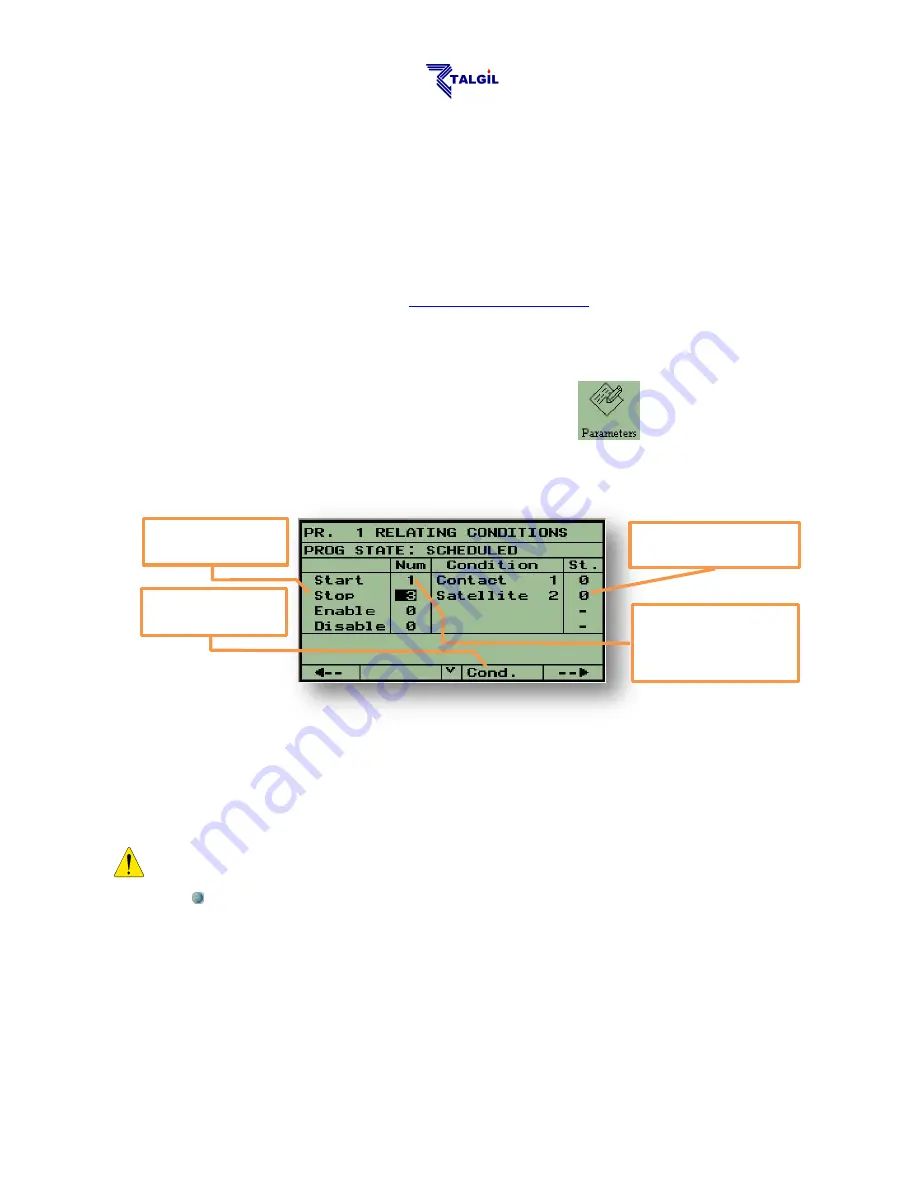
condition becomes TRUE. For example in the above screen, program 1 will be started 

by condition 1 and will be stopped by condition 3 when they become TRUE. 


Notice that:  


  The 

Enable

  action  will  not  start  the  program;  it  will  only  permit  the 

program  to  run as  long  as  the  condition  is  TRUE  and  make  it  wait  as 
long  as  the  condition  is  FALSE.  Same  way  the 

Disable

  action  will 

cause the program to wait as long as it is TRUE and let it run as long 
as it is FALSE. 


Shortcut to 

Conditions Library


The current status of the 

condition is false


Condition No. 1 when 

becoming TRUE will 

cause the program to 

start


Possible actions on 

the program


Summary of Contents for DREAM 2

Page 1: ...COMPUTING CONTROL LTD NAAMAN CENTER HAIFA ACCO ROAD ISRAEL P O BOX 775 KIRYAT MOTZKIN 26119 TEL 972 4 9506050 9506051 FAX 972 4 8775949 E_mail talgil33 netvision net il 2016 THE DREAM 2 controller USE...

Page 2: ...2 3 2 Dosage by Volume Per Area 19 2 4 Local and Central fertilizer dosage 20 2 4 1 Global Accumulative fertilizers limit 21 2 4 2 Sequential fertilization 21 2 5 Irrigation Timing 22 2 5 1 Cyclic irr...

Page 3: ...o arrive 37 The Fert meter s ratio 37 The pulse length 37 Special case 38 8 7 Filter Sites Constants 38 DP Delay 38 Looping limit 38 8 7 1 What happens with the irrigation during backflushing 38 9 Uti...

Page 4: ...e a mediator between users and their controllers On the other end there are the controllers that also login to the SERVICE and stay online The SERVICE will repeatedly interrogate all the online contro...

Page 5: ...seconds and eventually the Main menu of the DREAM application will be displayed The user should wait patiently until this stage is reached Function keys F1 F2 F3 F4 from left to right handle position...

Page 6: ...ch can be reached from any of the DREAM 2 application screens by pushing simultaneously the PgDn and PgUp buttons Pushing the F3 Shutdown button is the only safe way for shutting down the DREAM 2 cont...

Page 7: ...nd the Main Power Fuse have to be checked As mentioned above the yellow LED indicates that the charging voltage 13 9v DC for the backup battery is generated If this LED does not light check the Chargi...

Page 8: ...ow LED ON The red LED of the USB will start lighting only after the Start Button is pushed indicating that the system is now up and running Together with the USB LED of the power supply board the red...

Page 9: ...d by Talgil and plugged into the CPU board Using an Ethernet card for connecting to a Local Area Network Using a USB Netstick plugged into the motherboard The controllers after power up use their inte...

Page 10: ...tem For setting up the internet communication there are some parameters to be defined The setting of these parameters is the job of the technical person in charge of the system installation Those who...

Page 11: ...ects is done by placing the cursor black background on the desired icon and hitting the ENTER key For getting back to the MAIN MENU from any screen use the key at the bottom rightmost corner of the nu...

Page 12: ...subject STATUS showing current statuses of the system and its components IRRIGATION supplying tools for defining irrigation programs including tools for monitoring the irrigation process and tools fo...

Page 13: ...ill not appear in the Main Menu 1 7 The ABOUT screen Being at the MAIN MENU we can use the F2 About key to reach the following screen The About screen contains some valuable information and enables ex...

Page 14: ...on timing programs will be activated by conditions When only the first step is defined the program is considered NOT READY it cannot be activated but after completing the second step the program is co...

Page 15: ...L OPERATION one valve after the other TEMPORARY GROUPS valves of the same line to be irrigated together and CONSTANT GROUPS with a common dosage must be enabled at DEALERS DEFINITIONS STARTING TOGETHE...

Page 16: ...not be editable through the local MMI Using long sequences must be enabled at the DEALERS DEFINITIONS 2 2 The Water Dosage definition Each member of the sequence must have a water dosage defined in or...

Page 17: ...n must be enabled through the DEALERS DEFINITIONS Coordinated start of members of a sequence using the sign is meant mainly for coordinating the fertigation of various valves in order to eliminate con...

Page 18: ...sing by evaporation the amount of water to be irrigated by each valve is calculated automatically relieving the user from the necessity of calculating and defining the dosages per all the valves day b...

Page 19: ...The irrigation will be by time 2 3 2 Dosage by Volume Per Area For those who are used to think about irrigation quantities in terms of volume of water per a unit of area the DREAM offers the option of...

Page 20: ...units Bulk L continuous injection of the fertilizer quantity specified in liters Locate the cursor at the dosage mode field next to the desired fertilizer number Select the desired dosage mode either...

Page 21: ...er to use this option it must be enabled at the DEALERS DEFINITION In the sequential injection mode the fertilizers will be injected one after the other with some flushing of the fertilizer line takin...

Page 22: ...s nonzero the Run List disappears Defining the stop time is optional When defined it can be used in two ways 1 By default it defines the time that when it arrives the program is terminated 2 The secon...

Page 23: ...g with some additional parameters the Radiation sets are used How to define radiation sets is explained at the paragraph Radiation sets definition in the chapter dealing with Utilities How do we make...

Page 24: ...of the desired condition in the row of the desired action we create a relation that will cause the action to be executed when the condition becomes TRUE For example in the above screen program 1 will...

Page 25: ...l lines is enabled only in the WATER DOSAGE screen where the line number is specified ENABLE COMPLETION is an option that can be activated per each program individually Once activated the option remai...

Page 26: ...y The same screen can be used for manual activation of outputs Use F2 Manual and then locate the cursor at the desired output Use F2 again for turning the output ON OF A manually activated output is m...

Page 27: ...of communication with all the RTUs used by the system The type of the RTU channel can be recognized by the interface type appearing at the top left corner Int2W is the interface of a 2 wired channel...

Page 28: ...hether it is TRUE 1 or FALSE 0 The conditions can refer to the following types of events Contact depending on the status of a dry contact input whether it is OPEN or CLOSED changing from OPEN to CLOSE...

Page 29: ...zone will the condition be checked for being TRUE or FALSE Additionally conditions may cause a message to be sent when becoming TRUE The following screen that can be found to the right of the Conditi...

Page 30: ...om other sources Each midnight the whole table is shifted downward and location No 1 is updated from the weather station otherwise when there is no weather station connected location No 1 that contain...

Page 31: ...ctor number F1 F2 F3 and select per each injector the desired dosing mode and finally insert the desired quantity or desired proportion per each injector How do we use the fertilizer sets The picture...

Page 32: ...ption of viewing only the fault reports The events are arranged in a chronological order When entering the reports display the latest 4 events will be shown Use the key to view the earlier reports The...

Page 33: ...ion only Irrigation valves connected to a water meter will accumulate volumetric accumulation as well as time accumulation when irrigating by time 7 3 Sensors Logging results When analog sensors are u...

Page 34: ...r is supposed to be closed are considered illegal When the number of pulses exceeds the specified limit it indicates a fertilizer leakage that will be responded by stopping the irrigation of the relat...

Page 35: ...y last the specified delay Water Leakage limit Pulses received from the water meter of the irrigation line while it is supposed to be closed are considered illegal and when exceeding the limit will in...

Page 36: ...the valve under normal conditions the Minimal flow is the limit below which the flow will be considered LOW FLOW the Maximal flow is the limit above which the flow will be considered HIGH FLOW The fil...

Page 37: ...selected action Stop faulty injector continue fertilization with the other fertilizers Stop fertigation stop all fertilizers of the Fert Site but continue irrigation Stop irrigation both irrigation an...

Page 38: ...er Sites Constants Each filter site may have the following parameters defined DP Delay defines the period the DP contact has to remain closed in order for it to cause a flushing cycle to be started Lo...

Page 39: ...When the selected mode of operation is by Flow or by Nominal flow the user must specify the various combinations of pumps to be used for each flow level Each row of the table describes the flow and t...

Page 40: ...outputs Satellites are outputs that can be logically attached to other outputs so that whenever any of those outputs is activated the satellite will also be activated and remain active as long as at...

Page 41: ...ccording to their uses For irrigation measuring the water used by an irrigation line For network protection measuring the balance between the water going into and exiting from a particular network For...

Page 42: ...mula all the water meters feeding the network and on the negative side all the water meters consuming from the network Under normal conditions the result should be zero since all the water going into...

Page 43: ...h analog sensor and the range of its scale are defined in the following screen First select the sensor type and then define the minimal value at 4mA and the maximal value at 20mA columns Next the outp...

Page 44: ...temperature the frost protection program should be started in order not to let the crop temperature drop to the Critical temperature defined by the user The Dew point is calculated based on the ambie...

Page 45: ...1 6 1 18 to 13 6 6 13 to 9 5 4 9 to 7 4 3 7 to 4 3 2 4 to 3 2 1 3 to 1 1 0 2 18 to 13 4 9 13 to 10 3 8 10 to 7 2 7 7 to 5 1 6 5 to 3 0 4 3 to 2 0 7 3 18 to 12 2 7 12 to 9 1 6 9 to 7 0 4 7 to 5 0 7 5 t...

Page 46: ...of alarm events With the Alarm outputs various alarming devices can be activated The table below can be used for marking for each Alarm output in which cases it should be activated and whether it wil...

Page 47: ...to it differently The coefficient is expressed in When the coefficient equals 0 the radiation set is disabled Notice that The same Radiation set can be used by several irrigation programs 10 Filtrati...

Page 48: ...he interval to next flushing is halted By default backflushing will start always with the first filter station on site However there is an option to request through the DEALERS DEFINITIONS that the fl...

Page 49: ...aspects and he can make changes in the memory allocation Because of the sensitivity of the data changes will be permitted only after inserting a password 247 and only when the system is idle We think...

Page 50: ...ible by the user otherwise some subjects of the SETUP menu will not be permitted 9 10 11 12 13 14 15 The screen above is used for defining which of the fertilizer dosage modes will be revealed to the...

Page 51: ...l dosage modes 22 Default dosage mode defines the dosage mode that will be used as default whenever a new irrigation job is defined 23 Area units The units that will be used for defining the area cove...

Page 52: ...clude the same valve several times in the same sequence 33 Repeated flow problem halt when this parameter is set to Y and the system detects high flow or low flow problems three times consecutively on...

Page 53: ...he upper limit of each item 39 40 41 42 43 39 Num of Sequences defines the number of sequences that can be defined for being used in Irrigation programs 40 Num of Groups defines the number of groups t...

Page 54: ...S CONSTANTS FERTILIZER SITES CONSTANTS pH EC CONSTANTS FILTER SITES CONSTANTS CONSTANTS 4 6 GROUPS LIBRARY FERTILIZER SETS LIBRARY EVAPORATION TABLE SEAZONAL FERTILIZER LIMITS CONDITIONS LIBRARY IRRIG...

Reviews: