background image

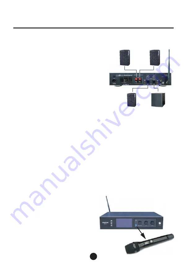
Left Main Speaker

Right Main Speaker

Active Center 

Channel Speaker

Active Subwoofer

EX-3

■ Quick Introduction to Frequency Matching

19


To make your wireless system work normally, the 

wireless handheld microphones and the power amplifier 

must be set to the same operating frequency.

Main Unit Settings


The general setup method is that the main unit and 

microphones


are kept within


sight and the


antenna is 

placed vertically.


Connect the power cord to the


main unit and turn on the 

panel power switch.


Use standard speaker binding posts to connect the outputs 

of the


main unit to passive speakers.


In the main interface, press the MIC A/MIC B button to 

enter the microphone receiver setting screen, rotate the 

encoder to change the frequency, and press the SYNC 

button to set the frequency.

Multifunctional Digital Power Amplifier

Wireless Handheld Microphone Settings


Insert two AA batteries into the wireless microphone and press the power button to turn it 

on.


The emitting window on the front panel of the main unit should be placed opposite to the 

infrared receiving window on the wireless microphone, and the distance should be kept at 

15-30 cm.


When the microphone is pairing with the main unit, the progress bar on the main unit 

screen will flash, and the wireless microphone screen will light up. When the channel on the 

wireless microphone screen is the same as that on the main unit screen, the pairing is 

successful.


Long press the EDIT encoder on the panel to return to the main interface, or wait 10 seconds 

Level Settings

:


When speaking or singing into the microphone, 

or using the microphone to connect to an 

instrument, it is at a normal level. Slowly adjust 

the volume of the panel to reach the level you 

want.


If you find that the system shows frequency 

interruption or burst noise, it may be due to 

interference from other frequencies. Please 

follow the steps above to change the channel of 

the system, or check whether the antenna is 

installed correctly.

Summary of Contents for EX-3

Page 1: ...User Manual DSP EX 3 Multifunctional Digital Power Amplifier A Combination of MIC DSP and Post Amp...

Page 2: ...g 19 04 Front Panel 20 05 Rear Panel 21 LCD 06 LCD Display 22 07 Wireless Microphone 23 07 Remote Control 23 Pc 08 09 PC Software 24 25 PC 10 14 PC Software Operation Instructions 26 30 15 16 Specific...

Page 3: ...48KHz 32 bit DSP 24 bit AD DA 9 4 LCD AA 4 200 VOD OPT COAX BT VOD SPDIF 5 5 5 DSP 16 USB 5 TFT 50 200 PLL 2X450 8 EX 3 EX 3 400 6828 333 02...

Page 4: ...EX 3 AA 15 30 EDIT 10 03 MIC A MIC B SYNC...

Page 5: ...1 3 4 2 5 6 7 8 EX 3 04 1 2 00 99 3 00 99 4 00 99 5 IR SENSOR 6 LED 7 TFT 8 MIC A A MIC B B SYNC...

Page 6: ...1 BNC 2 USB USB PC 3 4 REC 5 MIC PC 6 CENTER SUBWOOF XLR 7 VOD VOD 8 9 10 11 1 4 6 2 7 8 9 3 5 10 11 EX 3 05...

Page 7: ...1 2 3 4 5 VOD OPT COAX BT 6 7 8 1 2 3 6 5 8 7 4 EX 3 LCD 06...

Page 8: ...1 LCD 2 3 RF 4 AA 1 2 3 4 1 2 3 VOD OPT COAX BT 4 U01 U06 2 4 3 1 EX 3 07...

Page 9: ...USB PC USB USB PC EX 3 PC USB 1 PC 2 USB 3 PC PC USB 08...

Page 10: ...PC 1 2 3 4 5 EX 3 09 1 2 3 4 5...

Page 11: ...1 2 3 4 3 1 2 4 5 6 EX 3 PC 10 1 PEQ 2 VOD OPT COAX BT 3 4 1 PEQ EQ PEQ EQ PEQ 2 PEQ Q 3 PEQ PEQ 4 VOD SPDIF 5 6...

Page 12: ...3 4 5 8 6 1 2 7 EX 3 1 PEQ EQ PEQ EQ PEQ 2 PEQ Q 3 PEQ PEQ 4 BUTTERWORTH 6dB 24dB BESSEL 6dB 24dB LINK 12dB 24dB 5 6 4 7 8 11...

Page 13: ...5 7 6 4 1 2 3 EX 3 1 PEQ EQ PEQ EQ PEQ 2 PEQ Q 3 PEQ PEQ 4 5 6 7 12...

Page 14: ...3 4 5 1 2 6 7 EX 3 1 PEQ EQ PEQ EQ PEQ 2 PEQ Q 3 PEQ PEQ 4 5 0 100ms 6 7 13...

Page 15: ...2 4 5 6 3 7 8 EX 3 1 PEQ EQ PEQ EQ PEQ 2 PEQ Q 3 PEQ PEQ 4 20Hz 500Hz BUTTERWORTH 6 24dB BESSEL 6dB 24dB LINK 12dB 24dB 5 20Hz 500Hz BUTTERWORTH 6dB 24dB BESSEL 6dB 24dB LINK 12dB 24dB 6 0 100ms 7 8...

Page 16: ...20Hz 20kHz 6 3mm JACK 30dBu 2K RCA 12dBu 1M Stereo 5 0 Class2 4dbM 2 4G 24bit 48KHz 75 1 XLR 1 RCA 12dBU 500 32 bit DSP 48kHz 24bit sigma delta A D D A 5 TFT 480x854 RGB EX 3 4 750Wx2 8 450Wx2 THD 0...

Page 17: ...438 mm 320 mm 350 mm 88 mm EX 3 16...

Page 18: ...EX 3 2000 2000m 1 2 3 4 5 6 17...

Page 19: ...nd 5 TFT color touch screen for you to directly control the volumes of music microphone and effect and to perform functions of calling presets inputting selection Bluetooth playback interface micropho...

Page 20: ...tteries into the wireless microphone and press the power button to turn it on The emitting window on the front panel of the main unit should be placed opposite to the infrared receiving window on the...

Page 21: ...control and set a channel for the handheld microphone You can also use the functions with the remote control 6 Bluetooth Window The LED in this window will light up when Bluetooth is connected and lig...

Page 22: ...faces Connect and expand the other two wired and wireless microphones The input volume can be matched through PC software 6 CENTER SUBWOOF XLR Balanced Outputs These two output ports can be connected...

Page 23: ...put Selection VOD OPT COAX BT 6 User Preset Selection Different scene modes can be called 7 Input Level Display 8 Output Level Display Channel frequency Channel number 1 2 3 6 5 8 7 4 Battery power EX...

Page 24: ...o reverse the polarity of the batteries Note Do not insert the batteries backward because it will damage the microphone and you will not get a warranty 1 Mute Button Press it for the mute function and...

Page 25: ...turn on the power of the main unit The computer will automatically find the new hardware and prompt that the hardware is installed and ready for use 3 When you open the PC control software it will au...

Page 26: ...ng between Chinese interface and English interface 2 Connection Button One button connection with green light meaning Connected and blue light meaning Disconnected 3 Parameter Adjustment Area Conduct...

Page 27: ...ameters to display the frequency gain and bandwidth parameters of all PEQ points and click EQ reset to restore all PEQ parameters to factory default 2 The display area of PEQ parameters You can manual...

Page 28: ...ing frequency point Filter types low shelf high shelf low cut high cut and bypass function keys are available 3 The PEQ parameter slider can change the currently selected PEQ parameters frequency band...

Page 29: ...low cut high cut and bypass function keys are available 3 The PEQ parameter slider can change the currently selected PEQ parameters frequency bandwidth gain 4 There are mono and stereo options for ec...

Page 30: ...corresponding frequency point Filter types low shelf high shelf low cut high cut and bypass function keys are available 3 The PEQ parameter slider can change the currently selected PEQ parameters freq...

Page 31: ...slider can change the currently selected PEQ parameters frequency bandwidth gain 4 The low cut frequency of the subwoofer can be adjusted in the range of 20Hz 500Hz Low cut filter types include BUTTER...

Page 32: ...oth Input Bluetooth 5 0 Class2 4dbM frequency 2 4G Fiber Input 24bit 48KHz Coaxial Input 75 Front Output Port 1 set of balanced XLR 1 set of unbalanced RCA Front Output Level 12dBU Front Output Impeda...

Page 33: ...product Warning Risk of electric shock do not open Warning To avoid the risk of electric shock do not remove the cover There are no user serviceable parts inside When maintenance is needed please cont...

Page 34: ...r switch and unplug the power plug immediately and then send the product to the dealer for maintenance 3 The product and accessories should be placed indoors in a dry and ventilated place Do not store...

Page 35: ...18...

Page 36: ...9T00EX3S1A...

Reviews: