Function Descriptions
DG-U100
13
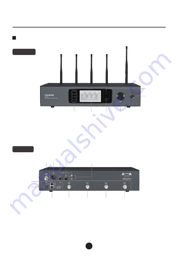
Control Unit Diagram
⑧
⑨
⑩
⑫
Note: Antenna frequency for Channel 1~4 is 640~690MHz
Front Panel
Back Panel
⑪
⑤
⑥
①
②
③
④
④
Edit button: rotate to move the cursor or edit
parameters, push to select or edit parameters
⑤ Power button
⑥ Infrared sync window
②
④
⑤
⑥
⑦
①
③
①
Channel 1~4 scheduling parameters
②
LCD display
③ Communication status
①
Power input socket
②
RS485 interface for high-
speed PTZ camera
③ Network RJ45 socket
④ Channel 4 antenna socket
⑤
⑥
Channel 2 antenna socket
⑦
Channel 1 antenna socket
⑧ RCA output socket
Channel 3 antenna socket
⑨
TRS isolated output
⑩
TRS non-isolated output
⑪
XLR balanced output
⑫
315 antenna socket
Wireless Conference Microphone System
Summary of Contents for DG-U100
Page 1: ...DG U100 WirelessConferenceMicrophoneSystem...
Page 4: ...DG U100 03 1 4 640 690MHz 1 4 RS485 RJ45 4 3 2 1 RCA TRS TRS XLR 315...
Page 5: ...DG U100 04 1 CURSOR 646 50MHz 31 11 11 06 A...
Page 10: ...DG U100 09 1 2 ID 3 ID 4 ID 5 8 ID ID 1 641 00 315 00 11...
Page 11: ...DG U100 10 1 2 3 4 5 6 2000 2000m...
Page 22: ......
Page 23: ......
Page 24: ......


