


For back-to-back and right angle mounting
(
Note
)
Applicable only to the sensor, not to the reflector.
(
Note
)
Applicable only to the sensor, not to the reflector.
Self-tapping
screws
Screws
Push rivet
②
③
①
BL-11
Reflector
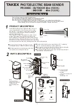
Installation with BL-11 (Sold separately)
①
Fix the first pole mounting plate with first pole bracket.
②
Pass the second pole bracket under the first pole
mounting plate and fix the second pole mounting plate
upside down.
※
Follow the same procedure as wall
mounting (from③) for wiring
①
Fix the BL-11 to the wall by 2 x self-tapping screws. (
φ
4x20mm)
(using keyhole)
②
Fix the reflector to the BL-11 by 2 x oval countersunk head screws
(M4x20).
③
Insert the push rivet into the lower hole in order to seal it.
⑤
6
WIRING
1
2
3 4
5
6 7
8
①②③④
}
}
①②③④
①②③④
}
}
}
}
①②③④⑤⑥⑦⑧
7
OPTICAL AXIS ADJUSTMENT
By aligning the optical axis correctly, a protection line with sufficient margin of sensitivity can be created, reducing the occurrence
of malfunction. Apply both “Distance check” and “Light reception level check” properly as shown below.
1 Before checking
③Supply power to the sensor.
When mounting is completed, adjust the lens unit
horizontally (left and right direction) to face the reflector.
Mount the reflector so that it directly faces the front of the
lens unit as much as possible.
The beam path should be as
close to parallel as possible to
ensure reliable operation.
Make sure that angle
remains within ±15 °
even if angled installation
is needed. When exceeding
this, the amount of reflected
light will be insufficient and
it will not operate correctly.
Lens unit
②Adjust the angle of the sensor with vertical adjustment screw
by looking through the viewfinder.
Continue adjust until the center of
the reflector can be seen in
the middle of
the viewfinder
as shown on
the right.
Power
10.5V to 30VDC
(non-polarity)
Tamper output
1b (N.C.)
30V (AC/DC) 0.25A
Tamper
Dry contact relay
output 1a/1b (N.O./N.C.)
30V (AC/DC) 0.25A
When cover
is detached
●
Example connection 1
●
Example connection 2
●
Example connection 3
Power
Power
Power
Alarm
Alarm
Alarm
Control panel
(12VDC)
Control panel
(12VDC)
Control panel
(12VDC)
Wire size
Voltage
DC24V
DC12V
500m (1,650' )
750m (2,500')
1,200m (4,000')
1,400m (4,600')
50m (165')
50m (165')
100m (330')
150m (500')
AWG 22 (Dia 0.65mm)
AWG 20 (Dia 0.8mm)
AWG 18 (Dia 1.0mm)
AWG 17 (Dia 1.1mm)
TERMINAL CONFIGURATION
●Wiring distance
CONNECTION
Alarm
output
Environmental
output
Environment
Current consumption (Max) : 200 mA (DC10.5V)
160 mA (DC12V)
80 mA (DC24V)
Vertically±5°
Horizontally±90°
Vertical
adjustment screw
Viewfinder
Inside the
viewfinder
Therefore, make sure to complete both
“2. Distance check” and “3. Light reception level check”.
Adjustment with the viewfinder may cause
some difference depending on the viewpoint
as it is only a rough adjustment.
Maximum wiring distance, when two or more sets are
connected, is the value above divided by the number of sets.
(
note
)
①