


③
4
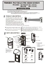
BEFORE INSTALLATION
L = Within 20m (66ʼ)
L = Over 20m (66ʼ) but within 30m(100ʼ)
L = Over 30m(100ʼ ) but within 40m(135ʼ)
W = More than 2m (6.6ʼ)
W = More than 3m (10ʼ)
W = More than 4m (13.5ʼ)
In above case, keep the
angle within ±15 °
Correct installation
● Parallel installation
φ
A
L
W
L
Do not perform multi-level protection or straight line protection
(3 spans or more), to avoid malfunction or lost alarm.
● Multi-level / straight line installation
Install the reflector directly, facing the front of the optical unit
as much as possible.
Reflection efficiency of the reflector, due to its nature, decreases
as the angle from the directly facing position increases.
Make sure that angle remains within ±15 ° even if angled
installation is needed. When exceeding this, the amount of
reflected light will be insufficient and it will not operate correctly.
※Align the center of the sensor with the center
of the reflector (the middle of the three reflector
plates) and mount them both keeping the
protection line horizontal. When mounting on
a pole, fix each pole mounting plate at the same
height to align the center of the sensor/reflector.
φ
A = 0.2×L
L = 10m (33ʼ ) :
φ
A =
φ
2.0m (6.6ʼ)
L = 30m (100ʼ) :
φ
A =
φ
6.0m (20ʼ)
MAX15°
OUTDOOR 0.5 to 30m (1.7ʼ to 100 ft.)
INDOOR 0.5 to 40m (1.7ʼ to 135 ft.)
POSITION OF INSTALLATION
INSTALLATION OF MULTIPLE SENSORS
CAUTIONS ON INSTALLATION
80 to 100cm
(31" to 39")
PROTECTION DISTANCE
*
HEIGHT OF INSTALLATION
Center of
the sensor
Center of
the reflector
Sensor
Sensor
Reflector
Reflector
Example 1
<Example>
Example 3
When BL-11 (optional) is used
Example 2
Right angle
.......................
....
...
In order to use this sensor correctly, thoroughly read this instruction manual and
select the mounting position and protection distance.
Straight line protection
(by mounting sensors
back-to-back)
Multi-level
protection
Straight line protection(3 spans or more)
In order to avoid malfunction or lost alarm caused by
interference, keep the distance between each sensor
when installated in parallel as below.
Install the sensor at a height of 80 to
100cm(31”to 39”) to catch a human
target. (Install vertically so that the
center of the sensor lens and middle
part of the reflector assembly are
placed at the same height.)
The optical unit can be adjusted horizontally
(±
90 degrees) and
vertically (
±
10 degrees) for various installation types.
(example 1 to 3)
Protection distance (between sensor/reflector)
should not exceed the rated range.
Outdoor protection distance may be reduced due to
the possible effect of mist, fog, frost, rain, or
condensation on the sensor unit
cover and reflector
unit, which can cause
false alarms.