


④
5
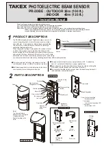
INSTALLATION
①
②
③
④
①
②
③
④
Grommet
※
※
※Recommended
for caulking
①
②
③
④
Cover
Mounting
plate
Heavy rain
NOTE : When installing the sensor on a wall without
roof or eaves, or where it is at risk from
exposure to heavy rainfall for prolonged
periods, we recommend caulking the top
side of the cover as shown below.
①
Remove cover from unit and slide the mounting plate
upwards to detach it.
②
Pull the wire through to the installation position.
③
Make one hole in the grommet on the mounting plate
and pull the wire through it. Secure the plate with 2 x
self-tapping screws. (
φ
4x30mm)
④
For exposed wiring, break knockouts (in 2 positions) on
the rear of the unit, pull the wire through as per the
diagram and attach it to the terminals on the sensor.
Wiring from
the bottom
Wiring from
the top
Knockout
Knockout
The grommet is compatible with a wire of
φ
3mm (
φ
0.12") to
φ
6mm (
φ
0.24") outer dia. When a wire of more than
φ
6mm (
φ
0.24")
outer dia. is used, cut
the dotted line portion on
the right figure using pliers
or similar.
Then use caulking to prevent
insects from entering the unit.
●Sensor
WALL MOUNTING
⑤
After wiring is completed, adjust alignment, attach
cover and check operation.
83.5mm (3.29")
Holes
Self-tapping screws
Pull the wire through the sensor body (back to front) and
attach it to the terminals on the sensor.
Grommet
●Sensor
●Reflector
●Reflector
※
Applicable pole size : Outside dia. 42mm (1.65") to 49mm (1.93").
※
Fix the pole mounting plates of the sensor and the reflector at the same
height to adjust them to each center.
127mm(5”)
58mm(2.28”)
Hood fixing screw
Self-tapping screws
(
Note
)
In case of outdoor installation, please do not remove hood.
POLE MOUNTING
⑤
Follow the same procedure as wall mounting (from③) for wiring.
Self-tapping screws
196mm
(7.72”)
Hood fixing screws
Push rivet
Push rivet
Hood
Upside down
Oval countersunk
head screws
Screws
Pole bracket
Pole mounting plate
Sensor mounting plate
(Remove it from the sensor body)
Reflector
Oval countersunk
head screws
Oval countersunk
head screws
Push rivet
Pole bracket
Pole mounting
plate
※
In case of indoor installation, the hood can be removed if it is not required.
Fix the reflector directly facing the sensor using
3 x (
φ
4x30mm) self-tapping screws
①
Loosen 2 x fixing screws on the top of reflector and remove the hood.
②
Remove the push rivet.
③
Invert the reflector with the hood fixing holes facing downwards and
fix into position with 2 x
(
φ
4x30mm) self-tapping screws using the
upper and lower holes.
④
Insert 2 x push rivets into the fixing screw holes to seal them.
①
Insert 2 x oval countersunk head screws (M4x20) into the pole
bracket with a few turns.
②
Position the pole between the pole mounting plate and the pole
bracket and tighten the screws.
③
Insert 2 x screws (M4x6)
into the pole mounting plate
with a few turns.
④
Fix the sensor
mounting plate
to the pole mounting
plate.
①
Insert 2 x oval countersunk head screws (M4x20) into the pole
bracket with a few turns.
②
Hold a pole between the pole mounting plate and the pole bracket
and tighten the screws.
③
Fix the reflector unit to the
pole mounting plate by
2 x oval countersunk head
screws (M4x20).
④
Insert the push rivet
into the lower hole
in order to seal it.