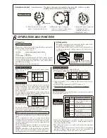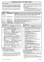
1. Turn power on.
2. Ignite a lighter etc. within detection area for more than the set time.
3. After the set time, an alarm output is issued, buzzer sounds intermittently and
LED blinks. (Alarm action)
4. 2 sec. after the flame goes off, alarm output ends. 10sec. after the flame
goes off, other alarm actions ends. (Check the alarm output by connecting
a device such like bell / siren.)
Do not use a lighter in no fire
zone because it is dangerous.
In such case, operation test
have to be done in other place
with sensor only.
●
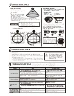
Detection area spreads out in
front of the sensor at approx.
120
°
conically.
Area locking screw have to be
turned with a big cross driver
until the inside of Lock window
changes to complete black
(FIXED : turn to right) or white
(LOOSENED : turn to left).
*
Sensor installation surface can be covered by the
most forward area setting.
After the adjustment, detach the sensor unit.
Fix the sensor head by turning Area locking screw to
right, and attach it again.
●
When improper area setting is found out by
operation check, adjust area setting.
●
The size of detection area is in
proportion to the size of flame
and the time of flaming.
The bigger flame becomes or
the longer flame continues, the bigger detection area becomes.
When small flame such like lighter's is the object to be detected,
confirm detection area.
Detection area
Approx. 120°
30°variable
10' (3m)
10' (3m)
20' (6m)
20' (6m)
30' (9m)
30' (9m)
33' (10m)
33' (10m)
30
°
variable
4 steps
7
DETECTION AREA
9
TROUBLESHOOTING
8
OPERATION CHECK
20'
(6m)
23'
(7m)
20'
(6m)
23'
(7m)
23'
(7m)
20'
(6m)
23'
(7m)
20'
(6m)
10'
(3m)
10'
(3m)
10'
(3m)
10'
(3m)
Solve possible problems according to the following table .
If normal operations can not be restored by these corrective actios, contact either
the dealer from whom you bought the unit or TAKEX.
Trouble
Completely inactive
Sometimes inactive
Activated without
flame
The alarm LED and
buzzer works but the
connected devices are
inactive
Check
●
No power supply (Broken wire or improper wire)
●
Low voltage (When power supply wired)
●
Sensor inside is wet by condensation etc.
●
Interrupting rays objects in front of detection area
(Glass, transparent resin are interrupting rays objects)
●
Improper area setting
●
Low voltage
●
Detection window is soiled with dust
●
Large electrical noise source such as a redio station or
high-voltage wire nearby
●
Sensor inside is wet by condensation etc.
●
Unexpected ultraviolet rays nearby (Ref : 2, ATTENTION)
●
Poor contact output connection or broken wire
●
The connected unit's trouble
●
Relocate the sensor to appropriate position
●
Correct power supply
●
Remove the dust and soil
●
Relocate the sensor
●
Dry out sensor inside, and remove the cause of wet
●
Remove the origin of the ultraviolet rays,
interrupt ultraviolet rays, or relocate the sensor
●
Check the wiring or connection
●
Check the connected unit
●
Correct power supply or replace broken
wire
●
Dry out sensor inside, and remove the
cause of the wet
●
Remove the interrupting rays object
Corrective action
Side view : Ceiling / wall mount
To be fixed
To be loosened
Area locking screw
Lock window
Front view : Ceiling mount
Top view : Wall mount
Condition of detection area
Detection timer : 0.2sec.
Origin of flame : Gas lighter
Size of flame : Approx. 2.75" (7cm)
●
固 定
→
←
→
←
1. DETECTION AREA
2. AREA ADJUSTMENT
LOOSENED
FIXED
Lock window
Lock window
Lock window
〈
Adjustment range
〉
Horizontal 25
°
………………
By base unit
Vertical 30
°
(4 steps)
………
By sensor head
sensor head


