background image

T-K3 Service Manual 

Ver. 1.05 

59


CONFIDENTIAL 

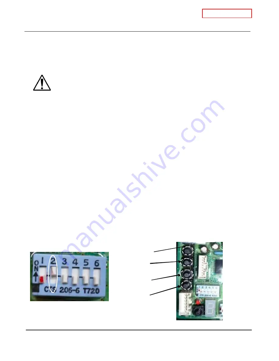
Figure 2 

12-15. Manually adjusting the fan motor speed


While the FM+ dipsw itch will automatically increase the fan speed by 6%, the fan motor 
speed on the T-K3 can also be manually adjusted.  In order to perform manual 

adjustments to the speed, a TM-RE10 or TM-RE30 remote controller is required.   


Manually adjusting the fan motor speed of the T-K3 w ill change the amount of intake 
air for combustion, w hich can cause excess CO emission from the exhaust chamber  

if the fan motor speed is set incorrectly.    Therefore, this procedure should 

never

 be 

performed unless Takagi USA has given consent and author ization. 


Adjusting maximum fan motor speed


1. While T-K3 is in operation, set dipsw itch No.2 to the “ON” position. ( Figure 1) 
2. On the temperature remote controller, display mode #3 (fan motor speed) by entering the 

“Diagnostics mode” (Refer to Section 12-1). 
3. Press and hold dow n the 

“MAX”

 button on the computer board.  While holding dow n the 

“MAX” button, press either the 

“INCREASE”

 or 

“DECREASE”

 button to increase or decrease 

the fan motor speed, respectively (Figure 2).    Refer to the remote controller display to verify that 
speed has been set to desired value. 
4. After fan speed has been set, set dipswitch No.2 back to the “OFF” position.


Adjusting minimum fan motor  speed 

1. While T-K3 is in operation, set dipsw itch No.2 to the “ON” position. ( Figure 1)


2. On the temperature remote controller, display mode #3 (fan motor speed) by entering the 
“Diagnostics mode” (Refer to Section 12-1).


3. Press and hold dow n the 

“MIN”

 button on the computer board.  While holding dow n the 

“MIN” button, press either the 

“INCREASE”

 or 

“DECREASE”

 button to increase or decrease the 

fan motor speed, respectively (Figure 2).    Refer to the remote controller display to verify that 
speed has been set to desired value. 
4. After fan speed has been set, set dipswitch No.2 back to the “OFF” position.


W ARNING 

T-K3 computer board 

Decrease button 

Increase button 

MIN button 

MAX button 

Figure 1 

Dipsw itch settings 

Summary of Contents for T-K3

Page 1: ...T K3 Service Manual Ver 1 05 1 CONFIDENTIAL T K3 Instantaneous Water Heater Service Manual TAKAGI Industrial Co USA Inc 5 Whatney Irvine CA 92618 Toll Free 888 882 5244 USA Toll Free 877 877 4953 CANADA ...

Page 2: ...main components in the interior view 6 5 Schematic diagram 7 6 Wiring diagram 8 7 Wiring diagram checkpoints for diagnosis 9 8 Resistance values of the temperature thermistors 10 9 Operational flow chart 11 10 Component specifications 12 11 Fault Analysis Specifications 32 12 Controls and settings 40 13 Components diagrams 65 14 Parts list 68 15 Revisions 70 ...

Page 3: ...WC Natural 0 4 WC LP 0 8 WC Natural 0 4 WC Flow rate 0 5 GPM to 7 0 GPM Available set temperatures 99ºF 185ºF default 122ºF 99ºF 167ºF Default 122ºF Temperature dipsw itch settings 104ºF 113ºF 122ºF 131ºF 140ºF 158ºF 176ºF 185ºF 113ºF 122ºF 140ºF 167ºF Bypass valve Yes N A Water control Thermisters 3 thermisters In Out Mixing 2 thermisters In Out Remote controller model TM RE10 TM RE30 TK RE02 PCB...

Page 4: ... 9 6 5 m m 1 3 8 36mm 1 1 2 37 8mm 3 5 8 93 3mm 4 1 2 1 1 4 2 m m 2 0 1 4 5 2 0 m m 13 3 4 350mm 1 1 2 37 8mm 1 3 4 45m m 1 3 4 45m m 10 2 54mm 2 1 3 8 5 4 4 m m 4 101 6mm 1 3 8 36mm 120V 4 7 8 124 3mm GAS 1 7 8 47mm 3 1 4 8 4mm COLD 5 1 4 132 9mm HOT 4 1 2 11 4 2mm 1 9 3 8 4 9 2 7 m m 1 26 3mm 2 3 4 72mm COL D 3 3 4 9 6 5mm 120V 5 3 8 1 36 1mm GAS 6 1 2 164 4mm HO T 9 1 2 241 3mm 1 5 8 4 2 5 m m ...

Page 5: ...on T K3 Part Takagi Part Common parts For other units 1 Case assembly 001 EKK1D SP 2 Combustion chamber 102 EKK1Y SP 3 Gas valve w ith Proportional valve 105 EKK1W OS SP 4 Computer board 701 EKK1L 5 Igniter 704 EKN74 TKJr TK1S TH1 OS SP 1 2 3 4 5 6 7 8 9 10 11 12 13 15 16 17 18 19 20 21 21 22 23 24 25 14 27 28 29 30 26 ...

Page 6: ...bly Burners 101 EKK1N OS SP 14 Hi limit sw itch 409 EKN34 TKJr TK1S TH1 OS SP 15 Fan motor 104 EKK25 SP 16 Freeze protection thermostat 705 EKJ59 TK2 TK1S OS SP 17 Flow sensor 402 EKK0T 18 Heat exchanger 401 EKK1X SP 19 Gas inlet 108 EKK1E OS SP 20 Exhaust 401 EKK1X 21 Heater 412 EKK2R OS SP 22 Flow adjustment valve 402 EKK0T 23 GFI 703 EKN73 TK1S TKJr TH1 24 Manifold 103 EKK1T NA EKK1S LP OS SP 2...

Page 7: ...at exchanger and is heated up to the set temperature 7 Using thermistors to measure temperatures the computer modulates the gas and w ater valves to ensure proper output w ater temperatures 8 When the tap is closed the T K3 w ater heater shuts dow n H O T C O L D G A S PCB Hi li mi t SW In le t dr ai n pl ug f il te r Mi xi ng Th er mi st or Dr ai n pl ug M ai n ga s va l ve Ga s s ol noi d v al v...

Page 8: ...een Y Yellow O Orange BR Brown SLAVE IN B K W R BK W R W R R Flow Sensor W Bypass Valve Flame rod Ground AFR rod Y G O Inlet thermistor Outlet thermistor Mixing thermistor Remote Controller Pump MASTER SLAVE OUT B K W B K W 6 5 4 3 2 1 B K BK BK BK BK BK BK B K W Flow Adjust ment Valve R R R R B K BK B K BK Multi system On line lamp 7 Seg LED 33 7 7 O FF 1 2 3 4 5 6 O FF P P P P BR B R B R B R MAX...

Page 9: ...Less than DC 1V and less than 1 3Ω C2 Overheat cutoff fuse Blue Blue Less than DC 1V and less than 1 3Ω D1 Black White DC 15V during Easy Link operation D2 Easy link connectors Black White DC 15V E1 Mixing thermistor Black Black E2 Outlet thermistor Black Black E3 Inlet thermistor Black Black See table on p 10 F Remote controller DC 11 25V Red Blue DC 110 160V Yellow Blue DC 13 17V Orange Blue DC ...

Page 10: ... 02 5 85 4 90 4 12 Temperature ºF 122 131 140 149 158 167 176 185 194 203 212 ºC 50 55 60 65 70 75 80 85 90 95 100 Resistance kΩ 3 49 2 96 2 53 2 16 1 86 1 60 1 39 1 21 1 05 0 92 0 81 Temperature ºF vs Resistance kΩ Temperature vs Resistance kΩ Temperature 0 00 5 00 10 00 15 00 20 00 25 00 20 40 60 80 100 120 140 1 60 180 200 220 Temperature ºF Resisitance kΩ 0 00 5 00 10 00 15 00 20 00 25 00 0 10...

Page 11: ...F SV1 OFF GPV OFF SV1 SV2 SV3 OFF STOP FM CLOSE the tap Flow sensor OFF Remove cause Opeartion lamp OFF OPEARTION OFF YES NO YES NO NO YES YES NO 20sec later YES NO NO YES YES NO YES NO 5sec later 3sec later YES YES NO YES NO 20sec later YES NO NO NO F YES FAV Flow Adjustment Valve B V Bypass Valve F M Fan Motor OHCF Over Heat Cut off Fuse M V Main gas Valve SV1 Solenoid Valve 1 SV2 Solenoid Valve...

Page 12: ...ame rod P 17 6 AFR rod P 18 7 Heat exchanger P 19 8 Flow adjustment valve P 20 9 Flow sensor P 21 10 Bypass valve P 22 11 Thermistors P 23 12 Hi limit switch P 24 13 Overheat cutoff fuse P 25 14 Heaters P 26 15 Computer board P 27 16 Transformer P 28 17 GFI P 29 18 Igniter P 30 19 Freeze protection thermostat P 31 AFR Rod Fl ame rod AFR Rod Fl ame rod ...

Page 13: ...K3 the gas rich burner stabilizes the flames within the combustion chamber and the air rich burner produces more heat in the combustion chamber The burners facilitate the air gas mixture necessary to produce the proper heat during the combustion reaction 1 Unable to initialize sustain combustion 2 Dust or soot deposit on the burner surface 3 Cracks on the burners 4 Gas leakage from burners 1 An un...

Page 14: ...to the burners The manifold has two types of the nozzles one type for gas rich burners 16 nozzles and the other for air rich burners 15 nozzles 2 There are 3 zones within the manifold to ensure efficient combustion operation 1 Dust deposit on the manifold 2 Gas leakage from a failed manifold 3 Ignition failure 4 Imperfect combustion 1 The burners cannot receive proper gas flow from the manifold wh...

Page 15: ... Voltage check proper range of voltages shown below 1 Fan speed failure causing abnormal sounds with or without combustion in the operation 2 Unexpected working caused by the connectors of the fan motor getting wet 3 Drops out from the bottom of the combustion chamber 1 T K3 does not function properly 2 Failure to ignite or abnormal ignition 3 Unstable combustion conditions DC 110 160V Input DC 13...

Page 16: ...nd resistance of coils proper range of values shown below Blue light blue Blue Orange 1 Gas leak from the unit 2 Excess carbon monoxide emissions 3 Lack of water temperature control 4 No flames Blue Red Modulates the gas flow from the gas inlet proportional gas valve Function Opens and closes the gas pathways of the T K3 main and solenoid gas valves 1 Gas leak from the valves 2 Unable to open clos...

Page 17: ... or soot buildup on rod 2 Check amperes proper range of values shown below To detect flames while unit is in operation 1 Unable to detect flames when flames actually do occur 2 Detecting a false flame when no flames actually occur 1 The T K3 stops operating The 111 and or 121 error code s will display 2 The T K3 will not initiate the ignition process The 721 error code will display during combusti...

Page 18: ... 2 Check voltages proper range of values are shown below Color Number of wires 1 Unable to detect flames when flames actually do occur 2 Detecting a false flame when no flames actually occur 1 The T K3 stops operating The 111 and or 121 error code s will display 2 The T K3 will not initiate the ignition process The 721 error code will display 3 The fan motor speed cannot be modulated properly unde...

Page 19: ...ide the heat exchanger pipes Scale buildup obstructs proper heat transfer to the water thereby overheating the heat exchanger and causing damage Absorb heat from combustion and transfer it to water through the heat exchanger pipes 1 Clogged heat exchanger fins and or cracks on the heat exchanger walls 2 Leaking exhaust gas 3 Improper heat transfer can cause the water in heat exchanger to boil 1 Wa...

Page 20: ... proper range of values shown below DC7 16V and 0 09 0 2kΩ Controls water flow to properly control the output hot water temperaturet 1 Water leakage from valve 2 The valve cannot modulate or make open close positions 1 Water leakage from failed valve can damage other T K3 components 2 Temperature fluctuations in the hot water output 3 Within a multi unit Easy Link system the 651 error code can occ...

Page 21: ...k u DC 4 5 5V Input 441 only within multi unit Easy Link systems Color Number of wires 1 Visual inspection connection breakage of wires and or debris on impeller 2 Check voltages proper range of values shown below DC 1 4V pulse 1 080 pulse min more than 18Hz Unable to detect or measure any water flow rate Ignition sequence does not start T K3 will not initiate any operation OUTPUT VCC GND 2 2 1 1 ...

Page 22: ...w temperature corrosion by reducing condensation buildup in heat exchanger Function 1 Mixes hot water from the heat exchanger with cold water from the water inlet in order to modulate and control the T K3 s outlet water temperature 1 Visual inspection connection breakage of wires 2 Check voltages and resistance proper range of values shown below 1 Water leakage from valve 2 The valve cannot modula...

Page 23: ...wires and or debris on thermistor 2 Check voltages and resistance proper range of values shown below Color Number of wires If the thermistors fail open or short error code appears before starting operation If resistance values are just off T K3 will have temperature fluctuations in hot water Inlet Black 42 Black Outlet Black 12 Black Mixing Black 113 Black 68 F 20 9 0 13KΩ 122 F 50 3 3 4 4KΩ 176 F...

Page 24: ...s of the heat exchanger After detection communication between the computer board and gas valves are severed shutting down the T K3 instantly The 111 or 121 error codes will display 1 Unable to detect excessively high water temperatures if switch fails closed 2 Continuous detection of excessively high water temperatures regardless of what the actual water temperature is if switch fails open 1 Unabl...

Page 25: ...er with a melting point of 365 F 185 C Detects excessive temperatures within the T K3 especially around the heat exchanger and combustion chamber Upon detection communication between the computer board and gas valves will sever shutting down the T K3 instantly The 111 or 121 error code will display 1 Unable to detect the excessively high temperatures within the T K3 1 Flames from burner may penetr...

Page 26: ...e the voltage needed to heat up Ceramic heaters do not activate allowing water contained in the heat exchanger to freeze up possibly causing the heat exchanger to burst The T K3 has two types of the heaters in it The one is for protecting of the heat exchanger and the outlet pipe the other one is for protecting of the inlet pipe N A AC 90 110V during operation 1 Visual inspection connection breaka...

Page 27: ...tic Color Number of wires Controls the functions of most of the parts in the T K3 Malfunctioning computer A component s may not operate within the T K3 In most cases of computer board failure the whole T K3 does not operate at all Error codes display N A Visual inspection connection breakage of wires and or burn marks on the computer board 701 721 741 991 761 during multi unit operation 6 1 2 16 5...

Page 28: ...less than 1Ω N A Color Number of wires 1 Visual inspection connection breakage of wires and or signs of electrical damage 2 Check voltages of the transformer Proper range of values shown below 100VAC less than 1Ω 1 There is no power coming from the transformer 2 The voltage from the power supply cannot be converted to 100VAC 1 The T K3 does not operate due to lack of power from transformer 2 A fai...

Page 29: ...e test button the GFI is receiving power After verifying the power supply verify that 100VAC is entering and leaving the GFI Detects electrical leakage in the T K3 Stops providing power to the T K3 in the case of electrical leakage 1 ON failure Always in the ON mode never trips 2 OFF failure Always in the OFF mode always stays tripped 1 ON failure GFI cannot detect electrical leakage within the T ...

Page 30: ...e 7 90 VAC 110 VAC To ignite the gas air mixtures when the T K3 is ready to burn gas on its burner surface The output voltage of the igniter is more than 14kV 1 Unable to ignite during the ignition process 2 Makes attempts to ignite at all times 1 The T K3 cannot ignite during the ignition process and the 111 or 121 error codes will display 2 No effects on the T K3 however the durability of the ig...

Page 31: ...nspection connection breakage of wires and or the body has been broken 2 Check resistance and voltage proper range of values shown below Temperature detecting device which prevents the pipes within the T K3 from freezing When this device detects temperatures below 36 5 F 2 5 C inside the T K3 power is supplied to the electric heaters to prevent the T K3 from freezing 1 ON failure Always senses fre...

Page 32: ...ure is enough 3 Check whether the temperature setting is too low The water is too hot 1 Check whether the temperature setting is too high 1 Make sure the unit gets a 120V 60Hz power supply 2 3 Check that the filter on the cold water inlet is clean 4 5 Check that the filter on the cold water inlet is clean 6 Check whether or not the unit is frozen 7 Check if there is enough gas in the tank for prop...

Page 33: ...rmal 0 09 0 2kΩ between red black The fan motor is still spinning after operation has stopped Nature of Fault Diagnosis The hot water turns cold and stays cold Check whether the flow rate enough to keep the T K3 running Check if there is a recirculation system installed and check also if the recirculation line has enough check valves Check that the fixtures are free from debris and obstructions C ...

Page 34: ...portional valve VG0 H1 Normal DC1 15V between white red 4 Gas solenoid valve fault Main gas solenoid valve MV fault C Normal 0 9 1 3kΩ between COM blue 3 light blue Gas solenoid valve SV1 fault Normal 1 3 1 9kΩ between COM blue 9 green Gas proportional valve VG0 fault H1 Normal DC1 15V between white red 5 Disconnected damaged O H C F C2 Visual inspection connection breakage of wires Normal 1Ω or l...

Page 35: ...ht blue Gas solenoid valve SV1 fault Normal 0 9 1 9kΩ between COM blue 9 green Gas proportional valve VG0 fault H1 Normal DC1 15V between white red 4 Check for soot on the flame rod I Clean the flame rod PCB fault Flame rod fault insulated resistance Normal 40KHz 60KHz orange green Error code is shown after three failed attempts at ignition Check the connection of ground wire make sure there is fi...

Page 36: ...ot buildup 391 331 321 Visual inspection connection breakage of wires 121 Error code is shown after three failed attempts at ignition Error Code Malfunction description Cancellation method Disconnected damaged hi limit switch Refer to section 10 12 Disconnected short circuited outlet thermistor Turn off the power or water supply Diagnosis E2 Visual inspection connection breakage of wires and or de...

Page 37: ... between red black or white black Error Code Malfunction description Cancellation method Error Code Malfunction description Cancellation method Fault of driving circuit for any of the gas solenoid valves MV SV1 SV2 and or SV3 Turn off the power supply The computer checks the condition of the main gas valve immediately after every operation and the conditions of the solenoid valves 6 hours after ev...

Page 38: ... will cease to display Diagnosis Visual inspection connection breakage of wires and or burn marks on the computer board Error Code Malfunction description Cancellation method False flame detection Turn off the power or water supply Diagnosis I Error Code Malfunction description Cancellation method Turn off the power or water supply Fault of preparation for the outlet thermistor operation Fault of ...

Page 39: ...rror Code Malfunction description Cancellation method Miscommunication between Master and Slave units for Easy Link systems Restoring proper cable connections among all the T K3s When the computer detects proper connections among all the T K3s 761 error code will cease to display Diagnosis Inspect cable connections between Master and Slave units Diagnosis Error Code Malfunction description Cancell...

Page 40: ...3 ON OFF conditions BTU requirements for Intermittent mode 50 12 8 T K3 ON OFF conditions BTU requirements for Continuous mode 51 12 9 Pump control ON OFF conditions Overview 52 12 10 Pump control ON OFF conditions BTU requirements for Intermittent mode 53 12 11 Pump control ON OFF conditions BTU requirements for Continuous mode 54 12 12 Multi unit system ON OFF conditions 55 12 13 Relay selection...

Page 41: ...3 Scroll to the desired T K3 unit either 1 2 3 or 4 by pressing the HOT or COLD buttons to scroll up or dow n 0 w ill yield information on the w hole multi unit system Fig 2 4 Once desired is displayed press the w hite button located under the Buzzer Stop button to select the either a particular T K3 unit or the w hole multi unit system The number 1 w ill then display right next to that selected F...

Page 42: ...ing the HOT or COLD buttons Fig 1 shows mode 5 being selected When selecting information please refer to the table on p 44 for the proper mode 3 Press the INFO button to select the mode and the information to w hich the mode correlates to w ill display on the TM RE30 Fig 2 4 When the ON OFF button is pressed or 5 minutes have elapsed w ithout pressing any buttons the display w ill return to normal...

Page 43: ...on about each of the individual T K3 s installed in the Easy link system In an Easy link system of T K3 s a maximum of 4 T K3 s can be linked together 4 Press the INFO button to select the desired unit 5 When the desired unit is selected and fixed scroll up or dow n to the needed information mode of the unit by pressing the HOT or COLD buttons Fig 3 shows mode 6 is being selected When selecting in...

Page 44: ...0ºF E5 under 32ºF E0 6 Output set temperature 99 to 185ºF Mixing temperature 32 to 210 ºF over 210ºF E5 under 32ºF E0 7 Operation time during current rotation 0 to 720 minutes After 720 thenext rotation occurs Air Fuel ratiorod current 0 to 999 0 1μA 8 ON OFF cycles during current rotation 0 to 100 cycles After 100 thenext rotation occurs Flow rate 0 to 999 0 1GPM 9 N A Bypassvalve position 0 to 9...

Page 45: ...on 3 If the computer board w orks properly the 7 seg LED shows the most recent error code in its error code history or a bar if there are no error codes saved to memory as show n in the picture to the right B Displaying error code history 1 Briefly press the error code button do not hold dow n the button 2 If the T K3 has had prior error codes the 7 seg LED w ill display the most recent error code...

Page 46: ... What is the altitude elevation of the area of installation 5 If installed indoors how long is the vent length 6 If installed outdoors w hat type of vent cap is used 7 Are there any obstructions in the intake air and or exhaust B How to clear the 991 error code after resolving the main root cause of the error On the computer board press and hold the INCREASE and DECREASE buttons simultaneously for...

Page 47: ...ressure Enable Disable Default 3 Changing the T K3 s ON OFF mode See Section 12 6 for details Continuous mode Intermittent mode Default 4 FM FM speed is i ncreased automatically by6 6 fan motor speed Disable Default 5 Deactivation of the freeze protection firing system Enable Disable Default 6 Freeze protection mode using circulation pump for T K3 s installed in recirculation systems Enable Disabl...

Page 48: ... the Increase button on the computer board The 7 seg LED w ill then display the assigned number for that T K3 unit for 10 sec NOTE In a single unit installation the numbering system is disabled B How to reset and reconfigure the numbering of units Unit s can be reset and reassigned manually 1 Press and hold the Increase button on the computer board of all slave units for at least 5 seconds 2 The 7...

Page 49: ...OFF Continuous mode Dipswitch set to ON Conditions needed to turn the T K3 ON The BTU requirement is more than 14 880 BTU h AND The w ater flow rate is more than 0 52 GPM The BTU requirement is more than 11 900 BTU h AND The w ater flow rate is more than 0 52 GPM Conditions needed to turn the T K3 OFF The BTU requirement is less than 11 900 BTU h OR Inlet temperature is higher than the set tempera...

Page 50: ...temperature at that moment w ill be 120 F C ON OFF table Flow rate GPM Set temperature F 1 0 1 5 2 0 2 5 3 0 3 5 4 0 ON 83 2 93 2 98 1 101 1 103 1 104 5 105 6 113 OFF 89 2 97 1 101 1 103 5 105 1 106 2 107 0 ON 92 2 102 2 107 1 110 1 112 1 113 5 114 6 122 OFF 98 2 106 1 110 1 112 5 114 1 115 2 116 0 ON 101 2 111 2 116 1 119 1 121 1 122 5 123 6 131 OFF 107 2 115 1 119 1 121 5 123 1 124 2 125 0 ON 11...

Page 51: ...perature at that moment w ill be 120 F C ON OFF table Flow rate GPM set temperature F 1 0 1 5 2 0 2 5 3 0 3 5 4 0 ON 89 2 97 1 101 1 103 5 105 1 106 2 107 1 113 OFF 98 1 103 1 105 6 107 0 108 0 108 7 109 3 ON 98 2 106 1 110 1 112 5 114 1 115 2 116 1 122 OFF 107 1 112 1 114 6 116 0 117 0 117 7 118 3 ON 107 2 115 1 119 1 121 5 123 1 124 2 125 1 131 OFF 116 1 121 1 123 6 125 0 126 0 126 7 127 3 ON 11...

Page 52: ...revious operation The BTU requirement is more than 11 900 BTU h Conditions that deactivate the pump 4 minutes after activation if the computer detects a BTU requirement of less than 18 600 BTU h the computer will stop the pump in 90 seconds Non stop pump operation Once the computer sends an ON signal to the pump it w ill never send a STOP signal The pump will continually run non stop as long as th...

Page 53: ...e and Tin Inlet temperature B Calculation example Set temperature Tset 122 F Flow rate 2 5 GPM Condition needed to turn the pump ON 122 Tin 2 5 500 18 600 Tin 107 1 F Condition needed to turn the pump OFF 122 Tin 2 5 500 18 600 Tin 107 1 F C ON OFF table ON values are the same as OFF values Flow rate of pump GPM Set temperature F 1 0 1 5 2 0 2 5 3 0 3 5 4 0 113 75 8 88 2 94 4 98 1 100 6 102 4 103 ...

Page 54: ...mp w ill continually run non stop as long as there is pow er to the T K3 B Calculation example Set temperature Tset 122 F Flow rate 2 5 GPM Condition needed to turn the pump ON 122 Tin 2 5 500 11 900 Tin 112 5 F C ON table Flow rate of pump GPM Set temperature F 1 0 1 5 2 0 2 5 3 0 3 5 4 0 113 89 2 97 1 101 1 103 5 105 1 106 2 107 1 122 98 2 106 1 110 1 112 5 114 1 115 2 116 1 131 107 2 115 1 119 ...

Page 55: ...rature Factor A F C GPM L min 100 122 37 50 3 4 13 131 55 3 2 12 140 60 2 9 11 149 65 2 6 10 158 167 70 75 2 4 9 176 185 176 185 2 1 8 2 Condition required to reduce the number of activated T K3 s A In the case of reducing down from 2 T K3 s to 1 T K3 Flow rate A 1 7 B All other cases Flow rate A n 2 3 Example Output set temperature 122 F in a 4 unit system and priority unit is No 1 To activate ad...

Page 56: ...p control please check the specifications of that particular relay to ensure that the current value through the coil w ill not exceed 1 amp For example To the right there is a sample of relay specifications from an arbitrary brochure You can select either the 120VAC or 240VAC relay because their current values are less than 1A 1 000mA Through this circuit the maximum current capacity is 1A Typical...

Page 57: ...n the computer board While holding dow n the MAX button press either the INCREASE or DECREASE button to increase or decrease the manifold gas pressure respectively Figure 3 Refer to the manometer to verify that pressure has been set to desired value 6 After gas pressure has been set deactivate the T K3 remove the manometer tube and replace the port screw Adjusting minimum manifold pressure 1 Ensur...

Page 58: ...T K3 Service Manual Ver 1 05 58 CONFIDENTIAL Figure 1 Manifold port Figure 2 To Manometer Tube T K3 computer board Figure 3 MAX button MIN button Increase button Decrease button ...

Page 59: ...ress and hold dow n the MAX button on the computer board While holding dow n the MAX button press either the INCREASE or DECREASE button to increase or decrease the fan motor speed respectively Figure 2 Refer to the remote controller display to verify that speed has been set to desired value 4 After fan speed has been set set dipswitch No 2 back to the OFF position Adjusting minimum fan motor spee...

Page 60: ...ture s activation requirements are met it is possible for both features to operate at the same time Automatic firing system Activation conditions w ill depend on the on w hether or it is an indoor direct vent or outdoor installation Gas and electrical pow er are required for this feature to operate Indoor direct vent installation After 5 minutes have elapsed since the T K3 s previous firing operat...

Page 61: ... temperatures of the inlet and outlet thermistors The automatic firing systemw ill not activate at all unless these 25 minutes have elapsed When the computer checks for these temperatures the freeze protection firing system w ill activate if Tin 37 F and Tout 43 F OR Tout 37 F where Tin is the temperature of inlet thermistor and Tout is the temperature of the outlet thermistor To sum it up in a ch...

Page 62: ...ermostat is located on the fan motor close in vicinity to the inlet and outlet pipes w ithin the T K3 Electrical pow er is required for this feature to operate The heating blocks w ill activate if the thermostat senses a surrounding temperature below 36 5 F Once they are on the heating blocks w ill only deactivate if surrounding temperatures reach above 46 4 F ...

Page 63: ...l not display anything on its 7 seg LED In addition the TM RE10 and TM RE30 remote controllers w ill also not display anything on its screen this is true w hether the T K3 is in a single unit installation or a multi unit Easy link installation A Activation conditions all 3 conditions must occur 1 The T K3 is in non operation no call for hot w ater 2 Dipsw itch No 6 the upper bank on the T K3 compu...

Page 64: ...Open all hot w ater taps in the house When the all water flow has ceased close all hot w ater taps 6 Have a bucket or pan to catch the water from the T K3 s drain plugs Unscrew the drain plugs to drain all the w ater out of the T K3 7 Wait a few minutes to ensure all w ater has completely drained from unit 8 Clean the filter Inspect the w ater filter located within the cold inlet With a tiny brush...

Page 65: ...al Ver 1 05 65 CONFIDENTIAL 13 Components diagrams 0 01 0 05 003 05 1 05 0 7 02 051 0 51 004 052 052 002 05 2 0 52 7 06 7 07 0 53 0 52 0 54 0 53 70 8 7 01 7 09 7 10 7 11 7 13 7 14 7 15 7 16 7 17 05 0 7 12 Case assembly ...

Page 66: ... 151 10 9 107 112 716 101 114 117 115 106 151 15 1 11 6 703 121 110 150 15 0 71 8 70 9 150 150 103 152 1 51 151 11 9 12 0 123 159 105 1 18 150 1 56 1 11 1 04 157 705 711 153 113 1 54 155 7 19 1 52 15 4 704 720 122 108 052 150 054 158 Burner assembly ...

Page 67: ...l Ver 1 05 67 CONFIDENTIAL 4 09 45 1 403 452 459 413 4 12 454 458 460 401 411 415 410 402 457 452 404 052 418 4 56 407 4 17 416 45 3 412 454 458 405 456 408 450 4 06 45 0 052 419 455 4 56 414 4 58 454 Water way assembly ...

Page 68: ...EK270 FAN DAMPER 112 EKN61 ROD CAP TKJr TK1S OS SP TH1 113 EKK2Z GAS INLET RING OS SP 114 EKK2V BURNER WINDOW OS SP 115 EKK2W ROD HOLDER GASKET OS SP 116 EKK32 ROD HOLDER OS SP 117 EKK0G BURNER HOLDER GASKET OS SP 118 EKK2D PRESSURE PORT SP 119 EKK2N URETHAN TUBE SP 120 EKK2Y MANIFOLD GASKET OS SP 121 EKK20 GFI PLATE 122 EKK1B IGNITER PLATE 123 EM167 WIRE CLAMP 60 TK2 TKD20 TKJr TK1S OS SP TM1 TM1...

Page 69: ...M TKJr TK1S OS SP TH1 454 EZM14 O RING P14 EPDM OS SP 455 EZM06 O RING P6 EPDM TK2 TKD20 TKJr TK1S OS SP TM1 TM199 TH1 456 EZM04 O RING P4 EPDM TK2 TKD20 TKJr TK1S OS SP TM1 TM199 TH1 457 EM192 FASTENER 16A TK2 TKD20 TKJr TK1S OS SP TM1 TM199 TH1 458 EKK24 FASTENER 14 22 OS SP 459 EKK39 FASTENER 16 25A OS SP 460 EKH30 FASTENER 4 11 TH1 701 EKK1L COMPUTER BOARD 702 EKH09 TRANSFORMER TH1 OS SP 703 E...

Page 70: ... changes Date 1 00 Sample evaluation 10 19 07 1 01 Revision of w rong information in the section 10 11 and 12 10 28 07 1 02 Revision of w rong information in all section 11 28 07 1 03 Revised by P P 1 14 08 1 04 Revised by P P 2 20 08 1 05 Revised by the R D and Takagi Japan 3 4 08 ...

Reviews: