M805-00
Initial Programming & Adjustment
7.3
Copyright TEL
30/09/96
7.1
T805 ASP Cards
7.1.1
Introduction
The initial adjustment procedure consists of defining the card type via DIP switches
SW301 & SW302 and setting the audio input and output levels. To simplify the system
set-up procedure, all T805 ASP cards (i..e. all TSGMs, LEMs, AIMs and ARMs) have
their input sensitivities and output levels set to -10dBm.
Audio is injected into the T805 ASP card via a 600
Ω
balanced line or a 47k
Ω
balanced
line, depending on the type of card being adjusted (TSGM, LEM, AIM, ARM) and the
audio distribution network into which the Quasi-Synchronous System is being inte-
grated.
Note:
The following procedure assumes the T805 ASP card is fitted in a T805-04
backplane or a T805-06 1U rack. A T1560-05 rack extension card is recom-
mended for ease of potentiometer adjustment.
7.1.2
DIP Switch Settings
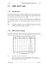
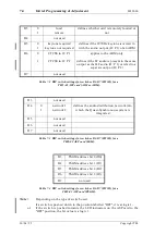
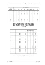
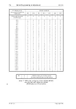
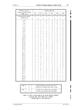
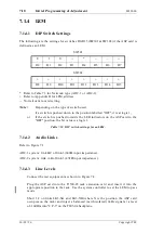
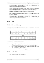
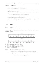
The 16 DIP switches (D0-D7 of SW301 & D8-D15 of SW302) on the ASP card uniquely
define what type of card it is and the various operating parameters it needs to operate
correctly. These operating parameters are described in Table 7.1 to Table 7.8.
Table 7.1 DIP switch settings for switches D0-D2 (SW301) for a
T805 ASP card.
Note:
Depending on the type of switch used:
if a switch is pushed down in the position labelled "OFF", it is at logic 1;
or
if the switch is pushed towards the LED indicators on the ASP card to the
"OFF" position, the bit value is a logic 1.
D0
D1
D2
Function
0
0
0
AIM
1
0
0
ARM
0
1
0
LEM
1
1
0
not used
0
0
1
TSGM
1
0
1
test mode 1
0
1
1
test mode 2
1
1
1
test mode 3
Summary of Contents for T805
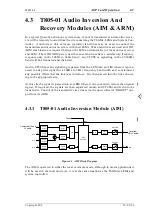
Page 16: ...4 2 ASP Card Operation M805 00 30 04 95 Copyright TEL ...
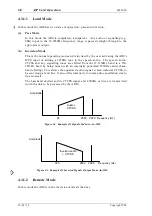
Page 44: ...7 18 Initial Programming Adjustment M805 00 30 09 96 Copyright TEL ...
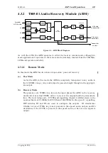
Page 70: ...14 1 2 PCB Information M805 00 30 04 95 Copyright TEL ...
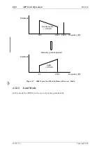
Page 89: ...Copyright TEL 30 09 96 M805 00 T805 Front Panel PCB Information 14 5 3 ...


