4.6
ASP Card Operation
M805-00
30/09/96
Copyright TEL
4.2
T805-02 Line Equaliser Module
(LEM)
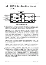
Figure 4.2 LEM Block Diagram
The LEM applies the audio signal equalisation (gain, phase and group delay) for the
transmitter to which it is associated. An LEM may be connected to only one transmitter.
Like the TSGM, the LEM has two modes of operation: training and normal.
The training procedure for the LEM is controlled by the System Controller. Training
audio consisting of high frequency (HF) training audio (300-2550Hz) and low frequency
(LF) training audio (45-300Hz) is passed from the TSGM into the LEM to be trained
where it is combined, processed and passed to the transmitter. A strategically located
monitor receiver passes the received audio back to the LEM where it is compared to the
reference tones (from the reference LEM). The characteristics (gain, phase and group
delay) are then modified (equalised) by the LEM to produce the same response as the
reference. When training of that LEM is complete, the speech audio passed into the
LEM is modified according to this characteristic.
The TSGM signals to all LEMs the beginning of each training sequence (which is initi-
ated by the system controller) via the "GPS" input of each LEM. Only the LEM being
trained will respond to it.
The audio inputs and outputs of the LEM may be configured in various ways, the sys-
tem configuration defining how these are selected (refer to Figure 4.2 and Section 5).
Under normal operating conditions the LEMs operate in the Quasi-Synchronous
("equalised") mode, but any LEM may be removed from Quasi-Synchronous operation
to operate independently if required ("breakout mode"). Control of this mode is via the
"ICCS" input of the appropriate LEM; normally held at logic "0", if pulled to logic "1"
(+5V) the LEM may be operated outside the Quasi-Synchronous system (i.e. the audio
being passed into the LEM is no longer modified and is usually transmitted on a differ-
ent frequency). An auxiliary audio input may be used for a different audio path when
this mode is invoked. If the training procedure is being carried out at the time the "brea-
kout" occurs, training is aborted. For more information on the training procedures, refer
to the System Controller manual.
A/D
Audio
amps
Audio
buffer
Audio
buffer
Audio
amps
A/D
Audio
buffer
Audio
buffer
Audio
amps
DSP
processor
D/A
D/A
Audio
amp
Audio
amp
Electronic
relay
Electronic
relay
1
3
4
2
1
2
HF audio
(speech or training tones)
LF audio
(CTCSS or training tones)
Breakout audio
(ADC-2 system only)
Monitor receiver
audio
N/C
GPS
ICCS
Start gun (synchronisation)
pulse
Breakout
control
Combined HF and
LF audio
Summary of Contents for T805
Page 16: ...4 2 ASP Card Operation M805 00 30 04 95 Copyright TEL ...
Page 44: ...7 18 Initial Programming Adjustment M805 00 30 09 96 Copyright TEL ...
Page 70: ...14 1 2 PCB Information M805 00 30 04 95 Copyright TEL ...
Page 89: ...Copyright TEL 30 09 96 M805 00 T805 Front Panel PCB Information 14 5 3 ...


