background image

OPERATING, MAINTENANCE 

4-13 


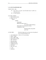
4.2.2. SYSTEM CONFIG  


For SYS CONFIG, there are 2 sub-menus, EDIT DATE and EDIT TIME. 

EDIT DATE


Press the “Enter” button to enter the current date. The format is mm/dd/yyyy. Use 

right

à

, left 

ß

 arrow keys to select the current month, and press “Enter” to go to 

the day column. Use two arrow keys to select the desirable day and again press 

“Enter” to edit the current year. Once the year has been selected and pressed 

“Enter”, the LCD display shows “Has Been Done!”. Now, press the “Exit” 

button to complete the setup of the date and go back to the upper menu. 

EDIT TIME 

Use right 

à

, left 

ß

 arrow keys to select this sub-menu under SYS CONFIG. 

Once selected, LCD display shows the current time first. Press “Enter” key again 

to edit the current time. The time format is hh/mm/ss. Use 

à

ß

 keys to select the 

hour in 24-hour mode, then press “Enter” to go to the minute column. Again, use 

2 arrow keys to adjust the minute and press “Enter” button to the second column. 

After these 3 time formats have been correctly edited, press “Enter”, the LCD 

display shows “Has Been Done!”, and then the current time starts to run and 

shows on the LCD display. Press “Exit” button to go back to the upper menu or 

“HOME” to the top menu. 

Summary of Contents for DT-2000 Series

Page 1: ...r TAINET COMMUNICATION SYSTEM CORP Headquarters No 25 Alley 15 Lane 120 Sec 1 Nei Hu Rd Taipei 114 Taiwan R O C TEL 886 2 26583000 FAX 886 2 26583232 Beijing Branch 5F A NO 1 Building 3rd Street Shang...

Page 2: ...aged to try to correct the interference by one or more of the following measures Reorient or relocate the receiving antenna Increase the separation between the equipment and receiver Connect the equip...

Page 3: ...ue your service temporarily If possible they will notify you in advance But the advance notice isn t practical you will be notified as soon as possible You will be informed of your right to file a com...

Page 4: ...3 2 COMMON INSTALLATION 3 2 3 2 1 The Front Panel Operation 3 2 3 2 2 The Rear Panel Connection 3 2 3 2 3 Clock Source Configuration 3 3 3 3 DT 2000F NF FULL E1 QUICK INSTALLATION 3 5 3 3 1 Setting a...

Page 5: ...ional E1 LCD Menu Tree E1 CF 4 7 4 1 4 The DT 2000NF LCD Menu Tree 4 9 4 2 OPERATION CONFIGURATION ADMINISTRATION AND MAINTENANCE 4 11 4 2 1 STATUS 4 11 4 2 2 SYSTEM CONFIG 4 13 4 2 3 SYSTEM ADMINISTR...

Page 6: ...CHAPTER 1 INTRODUCTION CONTENT 1 1 General Description 1 2 Specifications 1 3 Module List...

Page 7: ......

Page 8: ...over the frequency band from 0 Hz to 1168KHz into a 135 ohms termination Binary Digits Quaternary Symbol First Bit Sign Second Bit Magnitude 1 0 3 1 1 1 0 1 1 0 0 3 Table 1 1 The 2B1Q Line Coding l Th...

Page 9: ...side Communication range up to 4 5Km on 24AWG without line conditions Operate over loops line interfaces at data rate 1168Kbps per loop Utilizes 2B1Q line code with echo cancellation Full E1 functiona...

Page 10: ...eturn loss compliant with ETSI ETR 152 section 5 8 2 Performance test DLL model BER bit length compliant with ETSI ETR 152 section 5 9 6 3 Jitters tolerance compliant with ETSI ETR 152 section 5 9 3 7...

Page 11: ...d Loopback Customer Far End Loopback Data port loopback HDSL Digital Loop Self test Configuration backup and recovery to from external device Front panel switches Display far end Loop back test DT 200...

Page 12: ...140mA DC 48V input on each card l Environment Temperature Operating 0 C 50 C Storage 25 C 70 C Humidity Operating 10 90 non condensing Storage 5 90 non condensing l Physical DT 2000F Desktop Series H...

Page 13: ...X 21 Female with adapter cable Router Router Module Table 1 3 HDSL User Interface module list RACK POWER MODULE Model Module Description PWR 132A AC Power Module support Wetting Current for shelf mod...

Page 14: ...CHAPTER2 Unit Description CONTENT 2 1 General Description 2 1 1 Desktop Units 2 1 2 Rack Mounted Units...

Page 15: ......

Page 16: ...t without DTE interfaces module Full Fractional E1 menu selectable Optional DTE module V 35 Female V 36 Female with adapter cable V 21 Female with adapter cable G 703 2M balanced unbalanced Fig 2 1 Th...

Page 17: ...ns POWER ON E1 Green Indicates E1 LOS BER condition Off Means no LOS BER condition HDSL LED Green Indicates SNR of any HDSL loop is below a predefined threshold Off SNR of all loops are good LOOP 1 2...

Page 18: ...e Module Refer to the following demo diagrams v One RJ 45 Phone Jack for Balanced Application v One G 703 Unbalanced BNC Connector v V 35 Interface v RS530 l Fractional E1 Interface Module Refer to th...

Page 19: ...I MMCK manufacture test only don t change the setting E1 TX E1 RX SW1 JP1 Fig 2 9 G703B 3 2 048MBps G 703 Balance 120ohm interface module E 1 T X E 1 R X S W 1 JP1 SW1 Setup 1 OFF 2 ON 3 OFF 4 OFF JP1...

Page 20: ...module for Wetting Current Optional DTE module V 35 module with female adapter cable RS530 module female DT 2000NF2 HDSL Desktop Unit for Full E1 only E1 interface using G 703 balanced and unbalanced...

Page 21: ...3 4 5 6 7 8 S O O S O S O O JP V 35 RS530 G 703 SHORT OPEN Fig 2 12 DT 2000NF1 PCB JP 1 2 3 4 5 6 7 8 E n a b l e L o o p P o w e r D i s a b l e L o o p P o w e r O S S O O S O O JP1 JP8 JP12 JP15 SH...

Page 22: ...CONT SNR LOSW BER AIS RMT ALM TST SCAN HDSL E1 L1 L2 LOSW BER RESET Front Panel view of DT 2000N 1 2 3 4 5 6 7 8 Rx_Tip Tx_Tip Tx_Ring Rx_Ring 16 14 3 6 Rx Tx 5 2 DB25 BNC 1 8 DB 25 to BNC RJ 45 adapt...

Page 23: ...2 8 UNIT DESCRIPTIONS Fig 2 16 The rear panel view of TRS 32 Fig 2 17 The TRS 32 Daughter board TB 32 Fig 2 18 Terminal block insertion...

Page 24: ...SLOT 11 JP21 JP22 SLOT 4 JP 7 JP 8 SLOT 12 JP23 JP24 SLOT 5 JP 9 JP10 SLOT 13 JP25 JP26 SLOT 6 JP11 JP12 SLOT 14 JP27 JP28 SLOT 7 JP13 JP14 SLOT 15 JP29 JP30 SLOT 8 JP15 JP16 SLOT 16 JP31 JP32 Loop Po...

Page 25: ...ondition has higher priority than BER Yellow E1 BER condition E1 LOS BER LED Off no LOS BER condition Red HDSL Loop Power is inactive DT 2000NF2 only Yellow SNR of any HDSL loop is below a predefined...

Page 26: ...UNIT DESCRIPTIONS 2 11 This page is intentionally left blank...

Page 27: ......

Page 28: ...3 Clock Source Configuration 3 3 DT 2000F NF Full E1 Quick Installation 3 3 1 Setting as Co directional clock 3 3 2 Using different clock source 3 4 DT 2000F NF Fractional E1 Quick installation 3 4 1...

Page 29: ......

Page 30: ...BNC unbalanced E1 RJ 45 balanced E1 adapter DT 2000N Rack Mounted series only Rough handling during shipping causes most early modem failure after you unpack the modem check carefully for shipping dam...

Page 31: ...menu 5 Exit Key use it to go back to the upper level menu 6 Enter Key to enter the next lower level menu or confirm selections 3 Left Key to shift to left field of menu item 4 Right Key to shift to ri...

Page 32: ...eive side of E1 panel Rx Tip Ring cross connect Rx Tip Ring to the transmit side of E1 panel Tx Tip Ring HDSL RX TX HDSL Loop1 Loop2 RX TX Terminal RX TX E1 RX TX Terminal E1 Fig 3 5 An example of Lin...

Page 33: ...me Set E1 Clock E1 C NETWORK E1 C NETWORK DT 2000 DT 2000 DTE DTE Central Site Data Equipment Remote Site Data Equipment E1 CO E1 RT OSC Fig 3 7 DT 2000 E1 C Network clock supply When Clock source app...

Page 34: ...lock E1 C only When clock sources apply independently for CO and RT equipment v The CO site quick setup items from front panel are suggested as below 1 HDSL CONFIG SYSTEM TYPE E1 C 2 HDSL CONFIG E1 FR...

Page 35: ...peration example of menu tree are listed as below v Clock Source from DT 2000F Internal 1 HDSL CONFIG SYSTEM TYPE E1 C 2 HDSL CONFIG E1 FRAME FORMAT UNFRAME 3 HDSL CONFIG SET E1 CLOCK INTERNAL v Clock...

Page 36: ...res between CF RF v Turn on the power on all units v Configure the units using LCD panel or the Craft interface on the CF unit 1 The CO site E1 Fractional mode setup HDSL CONFIG SYSTEM TYPE E1 CF HDSL...

Page 37: ...RF v Turn on the power on all units v Configure the units using LCD panel or the Craft interface on the RF unit The RT site quick setup items from front panel are almost the same as CO site the system...

Page 38: ...o the equipment frame ground when handling cards Store cards only in anti electrostatic packaging provided by the factory 3 5 2 Card Installation Each shelf has a possible 16 slots Use the following i...

Page 39: ...built in G 703 E1 interface and one optional data interface for user to apply With the additional data port interface user can select ether G 703 V 35 R530 or both to connect with data terminals Anot...

Page 40: ...V 35 RS530 data interface 13 CF FmC NET G CO site with Fractional E1 Frame mode Network clock and V 35 RS530 data interface 14 CF FmC Int G CO site with Fractional E1 Frame mode Internal clock and V...

Page 41: ...3 12 INSTALLATIONS This page is intentionally left blank...

Page 42: ......

Page 43: ...ll E1 LCD Menu Tree 4 1 3 The Fractional E1 LCD Menu Tree for CO 4 1 4 The DT 2000NF LCD Menu Tree 4 2 Operation Configuration Administration and Maintenance 4 2 1 STATUS 4 2 2 SYSTEM CONFIG 4 2 3 SYS...

Page 44: ...the command and when necessary to select alpha and numeric information into the system l LCD The 16x2 char LCD panel is used for displaying menus and messages The LCD back light which is controlled b...

Page 45: ...S This screen shows you the current status of the selected status item Use RIGHT or LEFT key to see the next or previous status item l Command Confirm LOGOUT Are You Sure To confirm executing the comm...

Page 46: ...quit the editing press UP key l Alarm Display 1 EQ LIU0 1 N Board Fail U Y This screen shows an example of an active alarm The digit 1 indicates the number of the alarm EQ LIU 0 1 is the Access ID Th...

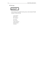
Page 47: ...M CONFIG Bad Privilege Various messages are provided for showing errors or current situations Possible messages are listed as following Access Denied Bad Privilege Privi Exipred No Carrier E1 in Servi...

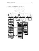
Page 48: ...IT TIME FRONT PANEL LOCK SET USER ACCOUNT SET SECURITY ACTIVE ALARMS SET ALARM LEVEL E1 LOS C E1 LOS R E1 Interface Only L1 LOSW L2 LOSW L1 Startup L2 Startup L1 CRC Err C L2 CRC Err C L1 CRC Err R L2...

Page 49: ...LD HDSL PA THRSHLD LOOPBACK TIMEOUT TIME SLOT GROUP HDSL PM CONFIG HDSL 15M PM REP HDSL DAY PM REP E1 15M PM REP E1 DAY PM REP REST LED TEST REMOTE TYPE REMOTE LED EXECUTE ACO E1 LOOPBK LOOP SELFTEST...

Page 50: ...T DATE EDIT TIME FRONT PANEL LOCK SET USER ACCOUNT SET SECURITY ACTIVE ALARMS SET ALARM LEVEL E1 LOS C E1 LOS R E1 Interface Only L1 LOSW L2 LOSW L1 Startup L2 Startup L1 CRC Err C L2 CRC Err C L1 CRC...

Page 51: ...HDSL PA THRSHLD LOOPBACK TIMEOUT BLOCK TIME SLOT HDSL PM CONFIG HDSL 15M PM REP HDSL DAY PM REP E1 15M PM REP E1 DAY PM REP REST LED TEST REMOTE TYPE REMOTE LED EXECUTE ACO FRAC E1 LOOPBK LOOP SELFTES...

Page 52: ...L2 Startup L 1 CRC Err C L 2 CRC Err C L 1 CRC Err R L 2 CRC Err R L1 SNR Bad C L2 SNR Bad C L1 SNR Bad R L2 SNR Bad R L1 BER Bad C L2 BER Bad C L1 BER Bad R L2 BER Bad R L1 PA Bad C L2 PA Bad C L1 PA...

Page 53: ...RSHLD HDSL PA THRSHLD LOOPBACK TIMEOUT BLOCK TIME SLOT HDSL PM CONFIG HDSL 15M PM REP HDSL DAY PM REP E1 15M PM REP E1 DAY PM REP REST LED TEST REMOTE TYPE REMOTE LED EXECUTE ACO FRAC E1 LOOPBK LOOP S...

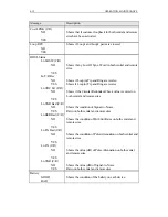
Page 54: ...Config Alarms YES Shows if alarm has been detected NO Service OOS Out Of Service IS In Service Selftest NO Shows if HDSL Selftest has been activated YES DP TYPE G 703 75 G 703 120 Shows the Data Port...

Page 55: ...ws if the Circular Redundant Check value is correct on both central and remote sites YES Ln SNR Bad C R NO Shows the condition of Signal to Noise YES Ratio on both central and remote sites Ln BER Bad...

Page 56: ...n to complete the setup of the date and go back to the upper menu l EDIT TIME Use right left arrow keys to select this sub menu under SYS CONFIG Once selected LCD display shows the current time first...

Page 57: ...EL from1 5 Level 5 has the highest privilege EXPIRATION DAYS from 001 999 days NUMBER DAY LEFT Display the number of days left for specific user SET SECURITY Define the privilege level for each user t...

Page 58: ...Attenuation threshold crossed LOSW DEFECT Loss of Sync Word defect LOSW FAILURE Loss of Sync Word failure COFA Change of Frame Alignment LOS DEFECT Loss of Signal defect LOS FAILURE Loss of Signal Fai...

Page 59: ...inute SASP Threshold Cross Alert T ESP 15MIN 15 minute ESP Threshold Cross Alert T SEFSP 15MIN 15 minute SEFSP Threshold Cross Alert T ESP 15MIN 15 minute ESP Threshold Cross Alert T CVL 1DAY 1 day CV...

Page 60: ...RK Central Office site Network or E1 C INTERNAL Central Office site Internal E1 SERVICE STATE OOS Select to Out Of Service to de activate all the E1 alarm detection IS Select to In Service to activate...

Page 61: ...US or CONTIGIOUS in one loop BLOCK TIME SLOT For E1 CF only Time Slot from 1 31 Use arrow keys to select for Block Prohibit Time Slot Press Enter to go to next time slot NULL DATA For DT 2000F NF 0Xff...

Page 62: ...le 4 4 HDSL Monitor Type Descriptions MON TYPE LOCATION DESCRIPTION FCP FCP FE Near End Far End Failure Count Path Count of Loss Of Sync Word LOSW failures on the HDSL loop CVP CVP FE Near End Far End...

Page 63: ...PTION CVL NEND Code Violation Line Count of Bipolar Violations BPV in the E1 signal LOSS NEND Loss Of Signal Second A second in which one or more Loss Of Signal defects occurred ESL NEND Erred Second...

Page 64: ...or one or more LOS defects CVP FE FEND Code Violation path Far end Count of FE Frame sync Errors or CRC errors SEFSP FE FEND Severely Erred Framing Second Path Far end Derived from Severely Erred Fra...

Page 65: ...s perform a lamp test Off To disable the RESET LED TEST LED Test To enable the LED test on selected module Local Soft Rst To enable Local Software Reset Local Hard Rst To enable Local Hardware Reset E...

Page 66: ...hen performs the boot up diagnosis Tests the E1 interface If the E1 interface pass the test the E1 LED will show green color otherwise red Starts up the HDSL loop During HDSL loop start up procedure t...

Page 67: ...NANCE EXECUTE ACO The ACO command is provided for operator to confirm the detection of an active alarm Are You Sure Once selected the Alarm Cut Off mode will be activated Has Been Done The LCD display...

Page 68: ...E 4 25 4 2 8 LOGOUT When select you will be asked Are You S ure Press ENTER to LOGOUT the current user the operator will be able to login for another user with different privilege level to monitor or...

Page 69: ...4 26 OPERATING MAINTENANCE This page is intentionally left blank...
Page 70: ...N x 64Kbps data port interface provide wetting current sealing current 000071 0002 DT 2000NF2 Provide Loop Power 000071 0005 V35 1A V 35 module 000046 0033 R530 1 RS 530 module 000046 0015 V36 1 R530...

Page 71: ...E4 DTE Received Line Signal Detector B 11 113b DA B 113b V 11 DCE3 DTE DTE Transmit Signal Element Timing B 12 114b DB B 114b 114b V 11 DCE4 DTE DCE Transmit Signal Element Timing B 13 106b CB B V 11...

Reviews: