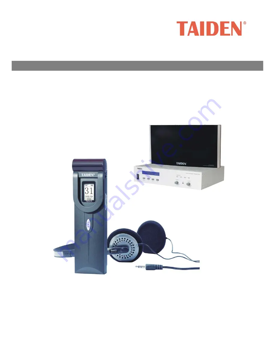
HCS-5100 Digital Infrared Language Distribution System
Installation and Operating Manual
V 1.10
Simultaneous Interpretation System
Page 1: ...HCS 5100 Digital Infrared Language Distribution System Installation and Operating Manual V 1 10 Simultaneous Interpretation System ...
Page 2: ... this manual The equipment must be connected to earth This product conforms to the rules of the European directive 2004 108 EC To protect your hearing avoid high pressure level on earphones Adjust to a lower and convenient level If any detailed information needed please contact your local agent or TAIDEN service center in your region Any feedback advice and suggestion about the products is appreci...
Page 3: ... the protection circuit of the battery and cause fire explosion leakage or heat generation 16 Unplug this apparatus during lightning storms or when unused for long periods of time 17 Refer all servicing to qualified service personnel Servicing is required when the apparatus has been damaged in any way such as power supply cord or plug is damaged liquid has been spilled or objects have fallen into ...
Page 4: ...he literature accompanying the appliance Attention Installation should be performed by qualified service personnel only in accordance with the National Electrical or applicable local codes Power Disconnect Units with or without ON OFF switch have power supplied to the unit whenever the power cord is inserted into the power source however the unit is operational only when the ON OFF switch is in th...
Page 5: ...ources 13 2 4 3 To emergency signal switch 13 2 4 4 To HCS 4385U 50 interpreter unit 13 2 4 5 To HCS 8300 Paperless Multi media Congress System 13 2 5 Menu structure 15 2 5 1 Transmitter menu structure work mode Master Analog 15 2 5 2 Transmitter menu structure work mode Master Interp U 16 2 5 3 Transmitter menu structure work mode Master Central U 17 2 5 4 Transmitter menu structure work mode Sla...
Page 6: ... Mounting on horizontal surface 34 3 5 Connecting to transmitter 35 3 6 Output power selection 35 3 7 Setting the radiator delay switches 36 3 7 1 System with one transmitter 36 3 7 2 System with two or more transmitters in one room 37 3 7 3 System with more than 4 carriers and a radiator under a balcony 39 3 7 4 System that mixes TAIDEN radiator with other brand compatible radiator 39 Chapter 4 D...
Page 7: ...e Case 51 7 4 1 Receiver HCS 5100R RA 51 7 4 2 Earphones 51 7 4 3 Ni MH Rechargeable Battery Pack HCS 5100BAT 16 52 7 4 4 Charging Case HCS 5100CHG 60 52 7 4 5 Storage Case HCS 5100KS 52 7 5 Connection details 52 7 5 1 Mains cables 52 7 5 2 Audio cables 52 7 5 3 Earphones 52 7 5 4 Emergency switch 52 7 6 Guaranteed rectangular footprints 53 7 7 Display language list 54 ...
Page 8: ...ystems Chapter 2 Digital Infrared Transmitter Detailed description of functions connection configuration operation and monitor function Chapter 3 Digital Infrared Radiator Detailed description of functions connection position planning installation of the radiator and using of power switch and delay switch Chapter 4 Digital Infrared Receiver Detailed description of functions operation using of test...
Page 9: ...ction 75 Ω HCS 5100T 35B 35W Digital Infrared Radiator r delay compensation function 75 Ω switching mode power supply without fan Digital Infrared Receiver HCS 5100R 04 08 16 32 4 8 16 32 CHs Digital Infrared Receiver LCD language display optional rechargeable battery pack or 2xAA alkaline cells HCS 5100RA 04 08 16 32 4 8 16 32 CHs Digital Infrared Receiver LCD language display 2xAA alkaline cells...
Page 10: ...ared radiation Delegates may now select a language on the infrared receiver and listen via earphone The system can also be used for other audio signal distribution occasions such as music distribution mono as well as stereo The HCS 5100 series is compliant to IEC 61603 7 Transmission of audio and or video and related signals using infra red radiation Part 7 Transmission system for digital audio si...
Page 11: ...tion 75 Ω HCS 5100T 35B 35W Digital Infrared Radiator r delay compensation function 75 Ω switching mode power supply without fan Digital Infrared Receiver HCS 5100R 04 08 16 32 4 8 16 32 CHs Digital Infrared Receiver LCD language display optional rechargeable battery pack or 2xAA alkaline cells HCS 5100RA 04 08 16 32 4 8 16 32 CHs Digital Infrared Receiver LCD language display 2xAA alkaline cells ...
Page 12: ...uency carrier signals typically 2 8 MHz to prevent interference by modern light sources Fully digital audio processing guarantees a constant high audio quality The signal processing in the transmitter consists of the following main steps see figure 1 3 1 Code each analog audio channel is converted to a digital signal the digital signals are compressed to increase the amount of information that can...
Page 13: ...r carrier depends on the selected quality modes Stereo signals use twice as much bandwidth as mono signals perfect quality uses twice as much bandwidth as standard quality A mix of channels with different quality modes can be chosen for each carrier with the total bandwidth not exceeding the available bandwidth The table below lists all possible channel combinations per carrier Figure 1 4 Standard...
Page 14: ...radiators the receivers will work well even in bright sunlight 1 3 2 Objects surfaces and reflections Just like visible light infrared radiation is reflected from hard surfaces and refracted by hyaloid glassy or transparent appearance objects Both objects in the conference venue and structure of the walls and ceilings will influence the distribution of infrared light Infrared radiation is reflecte...
Page 15: ...ted at 30 to the ceiling Figure 1 11 The radiator mounted perpendicular at 90 to the ceiling 1 3 5 Positioning the radiators Because infrared radiation can reach a receiver directly and or via diffused reflections it s important to take this into consideration when installing the radiators For best reception quality receivers should pick up direct infrared radiation In addition reflections will im...
Page 16: ...an the required intensity However due to the differences in the delays of the signals from two or more radiators the signals may cancel out each other multipath effect In a worst case situation loss of reception at some positions black spots may be the consequence Figure 1 14 and figure 1 15 illustrate the effect of overlapped footprints and differences in signal delays Figure 1 14 Increased cover...
Page 17: ...o other discussion and interpretation systems such as HCS 4385U 50 interpreter units or be used as a stand alone system for distributing external audio signals HCS 5100M is suitable for either tabletop or 19 inch rack mounting using Four feet for tabletop and two brackets for rack mounting are supplied Types HCS 5100MA FS 04N 08N 4 8 CHs Digital Infrared Transmitter compatible with HCS 4385U 50 or...
Page 18: ...9 2 2 Functions and indications Front of HCS 5100M N Rear of HCS HCS 5100MA FS N Rear of HCS 5100MA N Rear of HCS 5100MC N Figure 2 1 HCS 5100M N Digital Infrared Transmitter ...
Page 19: ...terpreter unit For connecting to HCS 4100M 50 or HCS 8300M congress main unit via CBL6PP 02 extension cable 15 DCS interfaces For connecting to HCS 4100M 50 or HCS 8300M congress main units 16 Extension interface For connecting to another transmitter under combination master slave mode 17 Fire alarm linked trigger interface When this switch is closed the emergency audio signal on the Aux R input i...
Page 20: ...g Then fasten the brackets with these screws and put the CMU in the cabinet Finally fix the four holes up with screws Figure 2 2 Installation of transmitter In addition 1U metal stripes are included as decoration to be installed between the transmitters in the cabinet It is also good for the ventilation and cooling off Fix up the four holes with screws Figure 2 3 Decoration of cabinet ...
Page 21: ...other transmitter in bypass mode Combination master slave mode HCS 5100M N series transmitter unique combination function can combine two N channels transmitter as one 2N channels system maximum 32 channels It can be achieved by setting the transmitter which is connected to radiator s to Master Analog mode the other transmitter to Slave mode One of the six radiator outputs of the slave transmitter...
Page 22: ...er unit HCS 4385U 50 interpreter units can be connected to the INTERPRETER S UNIT interface of HCS 5100MA F N Figure 2 9 Transmitter connected to interpreter units 2 4 5 To HCS 8300 Paperless Multi media Congress System HCS 5100MA F N connected to HCS 8300 Paperless Multi media Congress System HCS 8300M congress main unit can be connected via optical fiber interface 6P DIN interface or DCS interfa...
Page 23: ...14 Figure 2 10 HCS 5100MA FS N transmitter connecting to HCS 8300M congress main unit Figure 2 11 HCS 5100MC N transmitter connecting to HCS 8300M congress main unit through HCS 8300MO ...
Page 24: ...15 2 5 Menu structure 2 5 1 Transmitter menu structure work mode Master Analog Figure 2 12a Transmitter menu structure work mode Master Analog ...
Page 25: ...16 2 5 2 Transmitter menu structure work mode Master Interp U Figure 2 12b Transmitter menu structure work mode Master Interp U ...
Page 26: ...nu structure work mode Master Central U Figure 2 12c Transmitter menu structure work mode Master Central U 2 5 4 Transmitter menu structure work mode Slave Bypass Figure 2 12d Transmitter menu structure work mode Slave Bypass ...
Page 27: ...the simultaneous interpretation status will be displayed on the LCD Master Central U mode When the HCS 5100MA F N transmitter is connected to the conference main unit via the DCS 6P DIN interface the simultaneous interpretation status will be displayed on the LCD If the status is Bypass mode the display shows Work mode Monitor Channel If the status is Slave mode the display shows Connection status...
Page 28: ...o to the corresponding submenus To switch from term to term use the button To exit the current menu and to return to the upper level menu use the EXIT button 2 6 1 Work Mode a Use the button to switch between Master Slave and Bypass Master use the MENU button to confirm and go to step b Slave or Bypass use the MENU button to confirm and go to step c b Use the button to select the master mode inter...
Page 29: ...ting interface b Press the MENU button to switch channel number in the case of more than one channel Audio input indicates the current channel corresponding to the HCS 5100M transmitter audio input channel c After having selected channel number s use to adjust audio quality Audio mode includes Standard MONO Perfect MONO Standard STEREO Perfect STEREO The selectable audio quality depends on the cha...
Page 30: ...l output channels on the premise that fire alarm linked trigger interface is closed see section 2 4 3 Sensitivity Use the button to adjust the auxiliary input level range from 6 dBV 18 dBV Play Music a If Aux input type is Stereo music stereo or mono music from the auxiliary audio input will be distributed to all output channels MUSIC will be displayed at this moment b Use the MENU button to stop ...
Page 31: ...unction Setting a Press the button to select enable U disk function or not b Press the MENU button to save and return to upper level menu 2 6 11 Machine Rename Set alias for the HCS 5100M with a maximum length of 16 characters or less It is convenient to identify them on the operation of room combiner a Press the MENU button to enter the name setting interface the cursor blinks under the first cha...
Page 32: ...er Of Booth s Set Interlock Mode Between Booths Select Language Of Output Channel For Booth Operation steps a Setup the number of interpretation channels Use the button to switch the number of interpretation channels press and hold the button will adjust the numeric value quickly If 0 is selected it stands for no SI function use the MENU button to save and return to the main menu If other values a...
Page 33: ... language will be shown for each booth General procedure 1st step select a language for channel A 2nd step select ALL or NONE for channel C If ALL is selected for C then 3rd step select a language for B Three channels are now available A and B output a selected language and C outputs any available language If NONE is selected for C then 4th step select B NONE or ALL If NONE is selected for B only ...
Page 34: ...yed as in the following figure and can be adjusted Under channel state interface press MENU to select the channel number or parameter and press to change the channel number or parameter 2 6 18 Floor Distribution Setting Select distribution of floor audio to used simultaneous interpretation channels or not a Use the button to select Yes or No b Press the MENU button to save and return to the upper ...
Page 35: ...menu 2 6 22 Time Display Setting a Use the button to select Yes or No b Press the MENU button to save and return to the upper level menu 2 6 23 Play Floor on Unused SI Chs Play floor on unused SI channel or not a Use the button to select Yes or No b Press the MENU button to save and return to the upper level menu 2 6 24 Alarm Setting Enable alarm function or not a Use the button to select Yes or N...
Page 36: ...hone into the monitor earphone jack select the monitor channel with the monitor channel selector The audio signal input and the auxiliary audio signal input of the transmitter will be monitored The selected channel is displayed on the LCD After monitor channel selection LCD will return to transmitter status interface The monitor channel is updated to the channel selected at last Monitor volume can...
Page 37: ... off synchronously with the transmitter automatically If the radiator does not receive a carrier it switches to stand by state automatically If the radiator is overheating it will automatically switch from full power to half power or from half power to stand by state Types Digital Infrared Radiator HCS 5100T 15S 15W Digital Infrared Radiator delay compensation function 75 Ω HCS 5100T 25S 25W Digit...
Page 38: ...or 3 Input signal indicator 4 Fault indicator 5 Infrared emission area 5100T S Series Radiator HCS 5100T 35B Radiator Figure 3 2 Radiator rear Figure 3 2 1 Output power switch 2 Signal input 3 Synchronous output interface 4 Power supply 5 Angle adjust handle 5100T S series 135 10 gear HCS 5100T 35B 180 13 gear 6 Bracket ...
Page 39: ...30 5100T S Series Radiator HCS 5100T 35B Radiator Figure 3 3 Radiator side face Figure 3 3 1 Delay compensation indicator 2 Delay compensation switch 3 Output power switch ...
Page 40: ...lso be calculated with the footprint calculation tool available on the documentation CD ROM The given values are for one radiator only they do not take into consideration the beneficial effects of overlapping footprints and reflections see section 1 3 6 For up to 4 carriers experience shows that if the receiver can pick up the signal from adjacent radiators presumed radiators at a distance W their...
Page 41: ...ength from transmitter to radiator if possible see figure 3 7 Figure 3 7 Radiators with equal cable length If radiators are loop through the cabling between each radiator and the transmitter should be as symmetrical as possible see figure 3 8 The differences in cable signal delays can be compensated with the signal delay compensation switches on the radiators Figure 3 8 Symmetrical arrangement of ...
Page 42: ...d with both metric and inch screw plate and is compatible with most stand floor tripods Figure 3 9 Mounting on a tripod 3 4 2 Wall mounting A separate bracket HCS 5100TBZJ is optional for wall mounting refer to figure 3 10 The bracket can be fixed onto the wall with 4 screws Figure 3 10 HCS 5100TBZJ bracket Figure 3 11 Wall mounting 1 Figure 3 12 Wall mounting 2 Note When in operation the radiator...
Page 43: ...wall Figure 3 13 Wall mounting 3 3 4 3 Ceiling mounting The radiator can be fixed to the ceiling by using the built in bracket Please make sure to have enough space for a proper air flow around the radiator when selecting ceiling mounting In most cases a ventilator is needed to prevent overheating Figure 3 14 Ceiling mounting 3 4 4 Mounting on horizontal surface If the radiator has to be installed...
Page 44: ...nnected by daisy chain 3 6 Output power selection The radiator can be switched to half power output This is usually done when full power output is not needed e g when a portable system is used in a small venue Switch a radiator to half power if an adequate airflow cannot be guaranteed e g if the radiator is mounted on the top of an interpreter booth Reduce the power as often as possible to save en...
Page 45: ...tter There are no cable signal delays in systems with only one transmitter and radiators directly connected to the transmitter with cables of identical length The delay switches on all radiators are to be set to zero Subsequently check whether to compensate for radiation signal delay see section 3 3 3 If the cable lengths differ from radiator to radiator the delay switch parameter can be calculate...
Page 46: ...and Hall 2 2 Calculate the signal delay between the master and the bypass transmitter Table 3 2 3 Add the master to bypass signal delay to each radiator connected to the bypass transmitter in Hall 2 4 Determine the maximum signal delay 5 For each radiator calculate the signal delay difference by subtracting the cable signal delay from the maximum signal delay 6 Divide the signal delay difference b...
Page 47: ...50 250 250 25 10 Hall 1 T2 Master 30 30 5 0 150 0 0 150 150 500 150 350 350 25 14 Hall 1 T3 Master 40 40 5 0 200 0 0 200 200 500 200 300 300 25 12 Hall 1 T4 Master 20 20 5 0 100 0 0 100 100 500 100 400 400 25 16 Hall 1 T5 Master 50 50 5 0 250 0 0 250 250 500 250 250 250 25 10 Hall 1 T6 Master 30 30 5 0 150 0 0 150 150 500 150 350 350 25 14 Hall 2 T1 Bypass 50 50 5 0 250 250 250 250 500 500 500 0 0...
Page 48: ... 3 7 4 System that mixes TAIDEN radiator with other brand compatible radiator The radiators in above mentioned systems are all TAIDEN HCS 5100 Series Radiator The delay of electric input to light output of this radiator is 360 ns Other brands on the market have a higher electric input to light output delay for example 760 ns which means a 400 ns higher delay compared to TAIDEN HCS 5100 equivalent ...
Page 49: ...el selector volume control power switch Ø 3 5 mm stereo earphone jack and charging circuit on the PCB A LCD displays channel number with language name received signal intensity battery capacity and volume Types HCS 5100R 04 08 16 32 4 8 16 32 CHs Digital Infrared Receiver LCD language display optional rechargeable battery pack or 2xAA alkaline cells HCS 5100RA 04 08 16 32 4 8 16 32 CHs Digital Inf...
Page 50: ...the LCD 5 Power switch When the earphone is plugged in the receiver changes to stand by status Press the power switch to switch on the receiver Press and hold for 2 s will return to stand by status 6 Charging contacts Used for charging 7 Volume control An up down switch to adjust the volume the volume will be displayed on the LCD 8 Screw to fix the battery cover 9 Position for battery pack or disp...
Page 51: ...volume can be adjusted and displayed on the LCD To switch the receiver manually to stand by mode simply press and hold the on off button for more than 2 seconds If the earphone is disconnected the receiver is switched off automatically The infrared receivers are operable either with disposable batteries 2xAA alkaline cells or with a rechargeable battery pack HCS 5100BAT 16 Install the batteries or...
Page 52: ...cles such as a column an overhanging balcony or other large objects Check whether you used the correct footprints for the system design or not Check if the radiators used have a sufficient output power and b are not switched to half power operation by mistake If bad reception is caused by a blocked radiation path try to remove the blocking obstacle or add an extra radiator to cover the shaded area...
Page 53: ... the conference units via a Ø 3 5 mm stereo jack Suitable earphone types include EP 820AS single earphone EP 829 single earphone EP 829SW single earphone HCS 5100PA headphone EP 960BH headphone Any other compatible type see chapter 7 Technical Data ...
Page 54: ...45 4 6 Ni MH Rechargeable Battery Pack HCS 5100BAT 16 Ni MH rechargeable battery pack ...
Page 55: ...g unit Note Pull out the earphone before charging the receiver Switch on the charger before inserting the receiver Inserting and removing the receiver when the charger is powered on will not damage the receiver To maintain the service life of the Ni MH battery please charge it for 24 hours before first service until the charging indicator keeps lighting The charger supplies fast charge during the ...
Page 56: ...47 5 2 Storage case HCS 5100KS storage case is used to store and to transport IR receivers HCS 5100R RA It can contain 100 receivers in 1 storage case Figure 5 2 HCS 5100KS storage case ...
Page 57: ...d correctly Switch on the receiver and confirm that the channel indicator works properly Make sure that the receiver picks up sufficient IR signal and check the antenna signal intensity indicator Check the receiver by taking it in front of the mini radiator of the transmitter front panel Make sure that the volume is turned up Set the transmitter to test mode and check if the test tone is audible f...
Page 58: ...f an HCS 5100R receiver Audio frequency response 20 Hz to 10 kHz 3 dB at Standard Quality 20 Hz to 20 kHz 3 dB at Perfect Quality Total harmonic distortion at 1 kHz 0 05 Isolation at 1 kHz 80 dB Dynamic range 80 dB Weighted signal to noise ratio 80 dBA Cabling and system limits Cable type 75 Ohm RG59 Maximum number of radiators 30 per HF output Maximum cable length 300 m per HF output Maximum leng...
Page 59: ...iling mounting Mounting plates for floor stands Wall mounting bracket HCS 5100TBZJ can be used for fixing radiator to wall surfaces Dimensions H W D without bracket HCS 5100T 15S 25S 450 245 145 mm HCS 5100T 35S 500 305 145 mm HCS 5100T 35B 498 272 110 mm Weight without bracket HCS 5100T 15S 25S 5 kg HCS 5100T 35S 6 5 kg HCS 5100T 35B 4 2 kg Color HCS 5100T S B Dark red Electrical and optical char...
Page 60: ...820AS Single Earphone Used with the receiver conference unit Hi Fi sound quality Ø 3 5 mm stereo plug 32 Ohm Tip and Sleeve Ring NC Frequency response 50 Hz to 20 kHz Sensitivity 102 dBA 1 mW EP 829 Single Earphone Used with the receiver conference unit Hi Fi sound quality Ø 3 5 mm stereo plug 32 Ohm Tip and Sleeve Ring NC Frequency response 20 Hz to 20 kHz Sensitivity 108 dBA 1 mW EP 829SW Single...
Page 61: ...sumption standby 7 W no receiver in charging unit 7 4 5 Storage Case HCS 5100KS Physical characteristics Dimensions H W D 669 307 205 mm Weight 6 kg excl receivers 14kg incl 100 receivers excl batteries Color Blue 7 5 Connection details 7 5 1 Mains cables Blue Neutral Brown Live Green Yellow Earth Ground 7 5 2 Audio cables 3 pole XLR connector female Pin 1 Earth Pin 2 Signal Pin 3 Signal Chinch co...
Page 62: ...5 25 13 5 646 34 19 7 30 91 13 7 2 252 21 12 3 504 28 18 4 45 63 9 7 1 165 15 11 1 336 21 16 1 60 48 8 6 1 130 13 10 1 270 18 15 1 5 90 36 6 6 3 100 10 10 5 182 14 13 6 5 30 104 13 8 4 273 21 13 5 532 28 19 9 45 84 12 7 1 240 20 12 2 486 27 18 3 60 70 10 7 1 204 17 12 1 396 22 18 1 10 90 49 7 7 3 5 121 11 11 5 5 240 15 16 8 60 70 10 7 2 204 17 12 3 396 22 18 4 2 25 90 64 8 8 4 169 13 13 5 342 18 1...
Page 63: ...PAN 14 希伯莱语 Hebrew HEB 47 土库曼斯坦 Turkmen TUK 80 罗曼什语 Romansh ROH 15 匈亚利语 Hungarian HUN 48 乌克兰语 Ukrainian UKR 81 梵文 Sanskrit SAN 16 印度尼西亚 Indonesian IND 49 越南语 Vietnamese VIE 82 信德语 Sindhi SND 17 意大利语 Italian ITA 50 粤语 Cantonese YUE 83 僧加罗语 Sinhalese SIN 18 日语 Japanese JPN 51 克罗地亚语 Croatian HRV 84 梭托语 Sotho SOT 19 韩语 Korean KOR 52 斯洛伐克语 Slovak SLO 85 斯瓦西里语 Swahili SWA 20 马来语 Malay MAY 53 斯洛文尼亚 Slove...
Page 64: ...www taiden com TAIDEN INDUSTRIAL CO LTD Copyright by TAIDEN Last Revision 12 2014 ...