


3
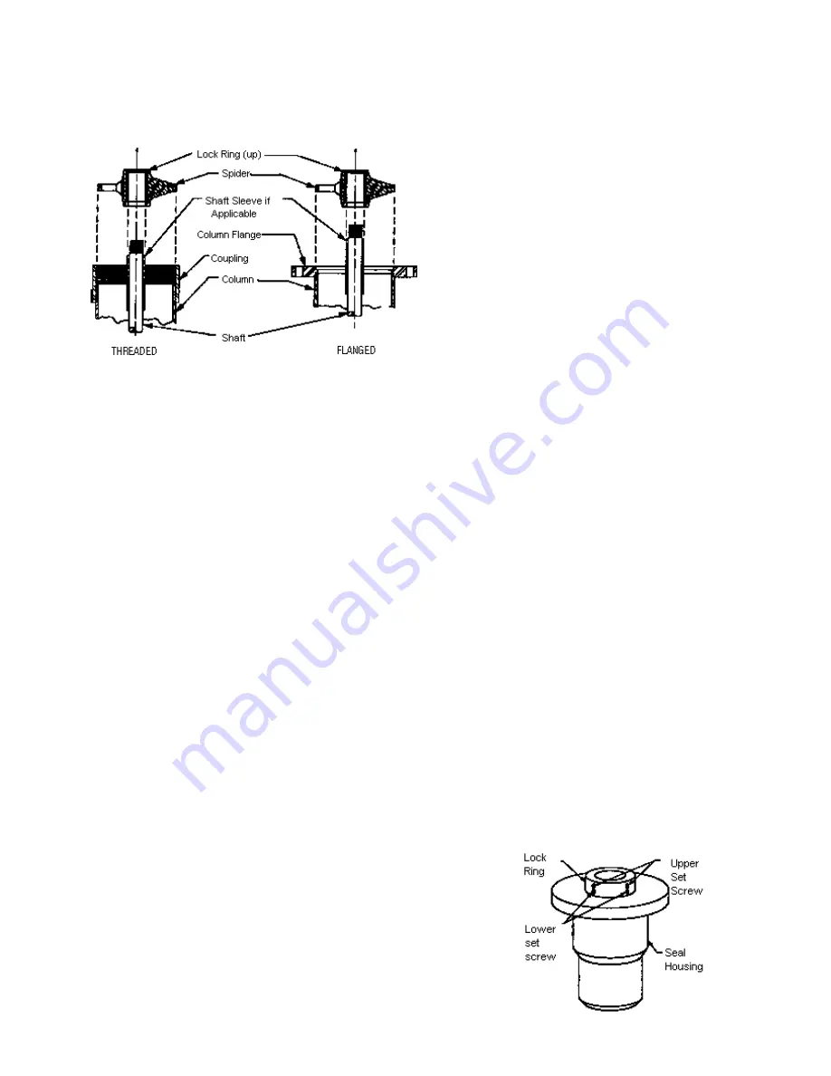
9.a If there is more than one section of threaded column, a center-
ing spider may be used. Slip the spider over the lineshaft with
lock ring on top. Screw the centering spider into the column
coupling until it butts against the column pipe. See Figure
A5.3.9 (THREADED).
Note: Some spiders may not have lock rings.
9.b If column is flanged, clean flange and the O.D. of the spider.
Slip the spider over the lineshaft with lock ring on top and
seat into spider recess. See Figure A5.3.9 (FLANGED).
10. Clean all lineshaft threads and faces thoroughly. Screw the
coupling on half of its length. Cover the coupling with a rag to
prevent foreign matter from dropping into the entrance.
11. If there is more than one section of column, repeat Section
A5.3, steps 1 through 10, for each additional section until all
of the column is assembled. Clean the thread/flange face of
the column pipe and the lineshaft projection thoroughly. Do
not attach the shaft coupling to the top piece of shaft.
A5.4: PUMP HEAD
1. Wipe a thin layer of joint compound on the top column
threads, or, if connection is flanged, on the top flange face.
Remove the packing gland assembly from the discharge
head or motor stand. Clean all machined faces of the dis-
charge head/motor stand thoroughly. Attach a sling to the
discharge head/motor stand, hoist and center over the col-
umn. Lower the discharge head/motor stand being careful
not to damage the top section of shafting, known as the
head shaft, or the stretch tube (if applicable).
2.a Set the discharge head on the top section of threaded col-
umn pipe. Screw the discharge head onto the column pipe.
2.b Align the holes of the discharge head/motor stand with the
holes of the column pipe flange, then lower until head is
resting squarely on flange. Install bolts and tighten.
3. If there is an underground outlet, place the head as close as
possible to the final position in relation to the outlet.
4.a If an adjustable top flange or threaded head is used, the
head can be readily turned to place it in alignment to the
underground outlet. In addition, the head should be turned
as needed to attain the proper shaft projection and the
correct distance from the outlet center line to the bottom of
the head. Back the packing ring off to allow ample working
room, fill the chamfer on the lower end of the flange with
lampwick packing that has been precoated with joint com-
pound. Use a generous amount of the packing and wind
the packing around in such a manner that it is screwed into
place. Screw the packing ring against the flange or bottom
of the head and tighten.
4.b If the adjustable flange is being used in conjunction with oil
tubing, the top of the tubing should be approximately 1
1
/
4
inches below the tension box mounting face of the head
after the flange is adjusted.
5. Hoist head slightly. Remove the clamp from the top piece
of column. Remove setting beams and clean surface of the
foundation itself. If there is an auxiliary line to the bowl bearing
or thermo-well, that portion immediately below and attaching
to the head should now be installed. Properly place discharge
outlet and align mounting holes with anchor bolts and lower
until head is resting squarely on the foundation.
6.a If head is resting on foundation plate, align mounting holes
of the head with tapped holes in the foundation plate. Install
and tighten cap screws.
6.b Mix a sufficient quantity of rather dry non-shrink grout. Force
as much grout under the foundation plate as possible. If
grout holes are provided, grout can be pressure-fed through
the grout holes until all cavities are filled.
6.c As the head is resting on the foundation, drive wedges
under head until proper elevation is within .005 inches of the
Total Indicated Run-out with respect to head shaft. Install
and tighten hex nuts to anchor bolts. Grout under the outer
perimeter of the head and cover the wedges with the grout.
6.d If a motor stand is used, as in an underground discharge
application, it should first be determined that the outlet in
the column aligns with the discharge piping so that no strain
will be placed on the pump. Do not make this correction
at this time, however. After checking the pipe alignment
follow Step 4a for leveling and grouting.
6.e Step 6d should be followed if there is a suction connection
to the header. It is recommended that a flexible joint of some
description be used between the suction flange and header
to compensate for any slight misalignment. If no flexible joint
is used, the header flange must be perfectly aligned so that
no misalignment is transferred to the pump.
A5.5: PACKING GLAND OR MECHANICAL SEAL
1. Packing Gland Open Line Shaft
1.a Remove the packing gland, packing rings and lantern ring
from the gland assembly. Clean the packing box thoroughly
and apply a neoprene o-ring to the receiving hole in the dis-
charge head.
1.b Slide the packing box over the head shaft. Properly adjust
mounting holes so that the grease ports of the packing gland
are directed toward the access windows of the discharge
head or motor stand. Seat the packing gland against the
discharge head/motor stand then install and tighten cap
screws. It should not be necessary to exert any side pres-
sure on the shaft in order to seat the packing box properly.
1.c Reseat packing. See Section G4 for details.
1.d Slip rubber slinger over head shaft and position just above
the packing gland.
2. Mechanical Seal Open Line Shaft
Figure A5.3.9
Figure A5.5


