background image

digipostpro with Clocking Module

digipostpro with Clocking Module

digipostpro with Clocking Module

digipostpro with Clocking Module    

Page - 24 


Digipostpro with Clocking Module 


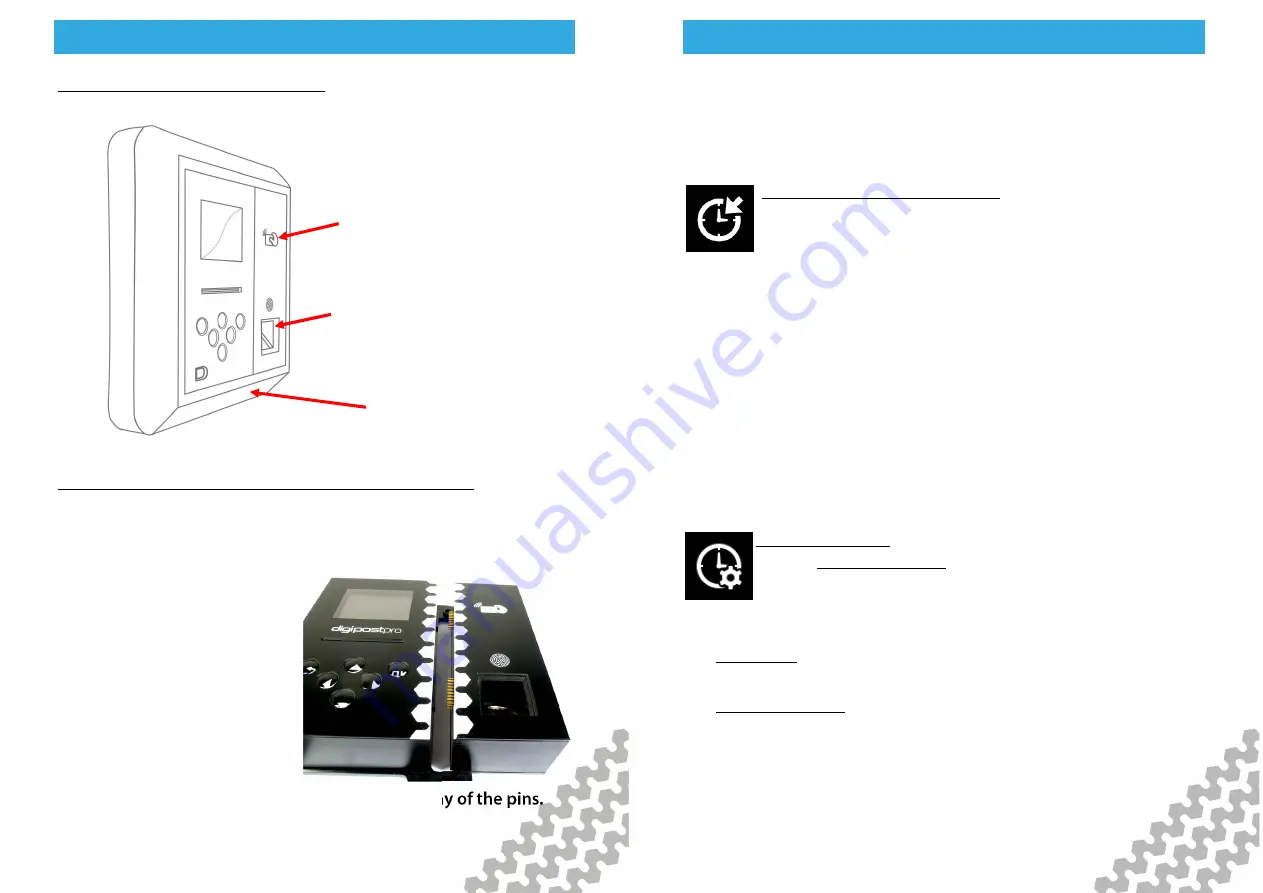
Hardware set up of digipostpro with Clocking Module 
To add the clocking module to a digipostpro ensure the base unit 
is not powered.   


First, remove the outer frame 
from the base unit (see page 
4). Then place the base unit 
and the clocking module on a 
flat surface and carefully slide 
them together, ensuring that 
all the pins are correctly 
aligned with the base unit 
connectors.  Alignment is 
extremely important in order to avoid bending any of the pins. 

RFID card/tag 

reader 

Finger print 

reader 

Large frame for 

clocking module 

digipostpro with Clocking Module

digipostpro with Clocking Module

digipostpro with Clocking Module

digipostpro with Clocking Module    

Page - 25 

 
Once the clocking module is connected to the base unit, follow 
the instructions for mounting the base unit to the wall (pages 4-
5). Once fixed to the wall, slide on the larger frame. 
 

Clocking set up on digipostpro 
See page 7 for accessing the configuration menu. 
 
Navigate to the Clocking settings. You are then given 

the option to change the function of each arrow button or view 
further clocking options. 
 
Changing the function of arrow buttons allows you to configure 
what each button does in the clocking process (once a user has 
got past the identification process of scanning their RFID card/tab 
and fingerprint).  You can configure the buttons how you wish 
(you can set them as  ‘unused’, clock in/out, or begin or end a 
break).  If you are using a driver card for clocking, you can also set 
any button to download the driver card along with any other 
function. 
 

Clocking Options 
    -  The Use Driver Cards option allows you to use driver 
cards for the purposes of clocking (see page 14).  Drivers 
can use their driver cards and non drivers can use RFID 

cards/tags.


    -  Allow Skip (on as default)- removes the option to skip after a 
fingerprint read failure 


    -  Allow re-register (on as default) this removes the option to re-
register a fingerprint against a clocking card after a fingerprint 
read failure. This function needs to be enabled in order to assign 
fingerprints to RFID cards/tags on setup. 

Summary of Contents for digiPostpro

Page 1: ......

Page 2: ...12 Files Analysis 12 13 Other Configuration Options 14 Maintaining and Transferring Files 15 20 Driver Cards and Driver Card Analysis 15 16 digivu 17 19 digifobpro 20 Archived Files 20 Configuring Yo...

Page 3: ...are Setup Hardware Setup Page 5 Cabling Inserting the module and fixing to the wall The outer frame has four break out tabs for cabling Clip the tabs with pliers or similar and feed the cables through...

Page 4: ...will now display the Main Menu Use the arrow buttons to navigate the options From within any sub menu simply press the return button to return to the previous menu and ultimately the main menu As a se...

Page 5: ...ess to save the settings selected Please note that the digipostpro has an internal battery which will keep the clock accurate if power is removed from the device Actual time is set from the server Con...

Page 6: ...iguration Menu Configuration Menu Configuration Menu Configuration Menu Page 11 digiConnect Specific to the LAN version of the digipostpro You can forward your files locally via digiConnect Select dig...

Page 7: ...iguration Menu Configuration Menu Configuration Menu Configuration Menu Page 13 File Options Choose File Options in order to change the archive status of files check uncheck the box by using the left...

Page 8: ...cation method i e modem LAN etc Maintaining and Transferring Files Maintaining and Transferring Files Maintaining and Transferring Files Maintaining and Transferring Files Page 15 Downloading Driver C...

Page 9: ...Drive Rest All modes Drive Rest Work POA Work Availability Time overlap Weekly 2 Weekly Within 24 Hours Break Maintaining and Transferring Files Maintaining and Transferring Files Maintaining and Tra...

Page 10: ...vu is connected to a VU the Download Activity LED will indicate the current stage of the download process A flashing orange LED indicates that the digivu and the Vehicle Unit are communicating A red L...

Page 11: ...figuring Your digivu Configuring Your digivu Configuring Your digivu Page 21 Configuring your digivu via the digipostpro To configure a digivu via your digipostpro the digivu menu option must be turne...

Page 12: ...nd will contain 4hz speed data which can be analysed with appropriate software Configuring Your digivu Configuring Your digivu Configuring Your digivu Configuring Your digivu Page 23 Driver Card By tu...

Page 13: ...e larger frame Clocking set up on digipostpro See page 7 for accessing the configuration menu Navigate to the Clocking settings You are then given the option to change the function of each arrow butto...

Page 14: ...ttons are configurable p 29 so menu may appear different to above image Clock Out End Break Start Break Clock In digipostpro with Clocking Module digipostpro with Clocking Module digipostpro with Cloc...

Page 15: ...Events and faults all faults recorded on the tachograph including overspeeds power inter ruptions and time adjustments Section 04 Detailed speed truck speed is recorded every second the truck is movin...

Page 16: ...Other Tachosys Products Other Tachosys Products Other Tachosys Products Page 30 Our hand held download tool selection Other Tachosys Products Other Tachosys Products Other Tachosys Products Other Tac...

Page 17: ......

Reviews: