SyxthSense Ltd
Copyright © 2018 SyxthSense Ltd. All rights reserved - 04/2018
PS
MOD3.103
- 12/23
Online store:
www.syxthsense.com
Enquiries: T:
44 (0)1392 875 414
E:
Configuration Parameters
Sensor 1 Source
Hardware
Input Settings
Sensor 2 Source
Network
Sensor 3 Source
Hardware
Digital Input Mode
Close for ECO
ENTER MAINTENANCE CODE FOR
MAINTENANCE MODE
CLICK TO ACCESS SETTINGS
GROUP
CLICK TO CHANGE
SETTING
ACCESS
MORE
SETTINGS
6666
8 9
5 6 -
2 3
Esc
OK
Del
Maintenance Code
Enter Code
7
4
1
0
Operating Modes
Parameter Groups
Display
Control Settings
Inputs
System
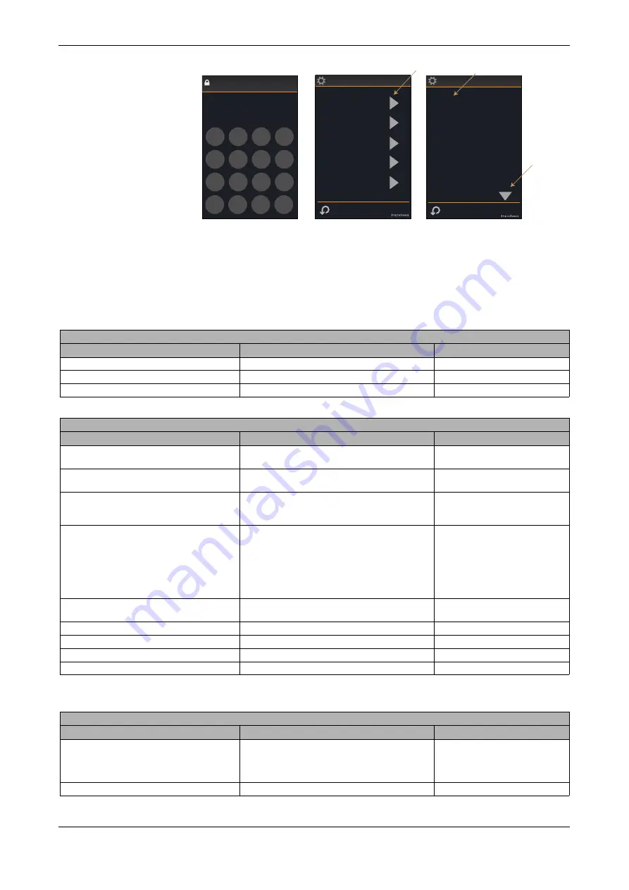
The SRI user interfaces are configured to operate in different modes via the configuration parameters
accessible through the maintenance mode.
To enter the maintenance mode click the COG WHEEL icon in the FURTHER SETTINGS SCREEN
and enter the maintenance mode password (default 6666).
Note:
The maintenance mode password can be changed in the configuration settings. Make sure that
you note the new password if changed.
CONTROL SETTINGS
Parameter Name
Description
Range
Nominal Setpoint
Nominal Setpoint
0.0...99.9°C/°F/% (Default 70.0°F)
Min Setpoint Adj
Minimum Adjustable Setpoint
0.0...99.9°C/°F/% (Default 57.0°F)
Max Setpoint Adj
Maximum Adjustable Setpoint
0.0...99.9°C/°F/% (Default 86.0°F)
INPUTS
Parameter Name
Description
Range
Sensor 1 Source
Sensor 1 Source. When set to Hardware reads RI1.
(status monitoring over the network is always active)
0 = Hardware (RI1)
1 = Network (Default)
Sensor 2 Source
Sensor 2 Source. When set to Hardware reads RI2.
(status monitoring over the network is always active)
0 = Hardware (RI1)
1 = Network (Default)
Sensor 3 Source
Sensor 3 Source. When set to Hardware reads the
internal temperature sensor.
(status monitoring over the network is always active)
0 = Hardware (Built-In Sensor) -
Default
1 = Network
Digital Input Mode
Digital Input Operation
(status monitoring over the network is active for all
modes)
0 = Disabled (no SRI effect)
1 = Close for ECO
2 = Open for ECO
3 = Close for OFF
4 = Open for OFF
5 = DI Contact Alarm
6 = Network
Digital Input Delay
Digital Input Delay Timer (transition from active to
non-active)
0..7200 seconds (Default 0s)
Internal Sensor Cal
Internal Sensor One Point Compensation
-10.0..+10.0 °C/°F
RI1 Cal
Sensor Connected to RI1 Calibration
-10.0..+10.0 °C/°F
RI2 Cal
Sensor Connected to RI2 Calibration
-10.0..+10.0 °C/°F
Humidity Cal
Humidity Calibration
-10.0..+10.0 % rH
OPERATING MODES
Parameter Name
Description
Range
Lock Mode
Lock Operation
0 = Disabled (default)
1 = On/Off/Boost Workable Only
2 = Temp Adjust Only Available
3 = No Input - All Buttons Disabled
Lock Mode Password
Lock Mode Password
0000 - 9999 (default 0000)


