background image


_____________________________________________________________________________________________________ 

Topvex SR07, SR09, SR11 E 


Installation instruction 


205870


Systemair AB


8

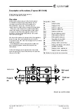
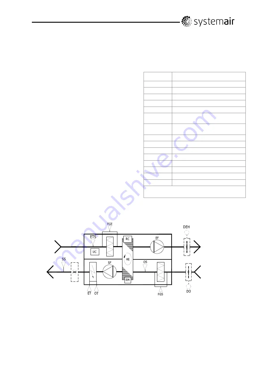
Description of functions (Topvex SR E EL) 


Electrical heating, extract air temperature 
control with cascade function. 
 

Function 

Start and stop times are set in the Control panel.  
To maintain constant room temperature the  
UC receives a signal from ETS and regulates  
the HE and the electrical heater in sequence.  
   The SS sensor is used to limit the max and min  
supply air temperature. Maximum temperature in the 
electrical re-heater is controlled by ET.  
OT disconnects the heater, gives an alarm signal  
and stops the appliance in case of overheating. 
 
DO closes the outdoor air damper when the 
appliance is stopped. In case of an unintended stop on 
the rotor, a signal is sent to RC, which is displayed on 
the Control panel as an alarm. 
   Also displayed in the Control panel are  
date and time, operating status, desired  
and actual room temperature. 
 
FGS and FGE give alarm signals when the 
actual value exceeds the pre-set desired  
value for pressure drop over the filter. 


Designation   Name 

EF 

Extract air fan 

SF 

Supply air fan 

SS 

Sensor, supply air 

OS 

Sensor, outdoor air 

ETS 

Sensor, extract air 

ET 

Sensor, max temperature in 
 the electric re-heater 

OT 

Sensor, overheating in the  
electrical re-heater 

FGE 

Filter guard extract air 

FGS 

Filter guard supply air 

UC 

Regulator Corrigo E28 

RC 

Control box for rotor 

RM 

Driving motor, rotor wheel 

HE 

Energy exchanger, rotor wheel 

DO 

Damper motor, outdoor air 

DEH 

Damper motor, exhaust air 

NB! Dashed components are accessories 

Drawn as a left version 

Supplyair 

Extract air 

Outdoor air 

Exhaust air 

Summary of Contents for Topvex SR07 E

Page 1: ...Corrigo ver no 3 0 1 03 Topvex SR07 SR09 SR11 E Compact Air Handling Unit Installation instruction GB GB...

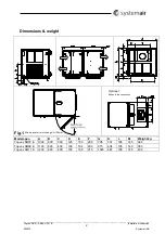
Page 2: ...struction 205870 Systemair AB 2 Dimensions weight Fig 1 Optional Exhaust top connection Model spec A B C D E F G K L M Weight kg Topvex SR07 E 1000 600 300 125 150 200 795 337 195 145 320 Topvex SR09...

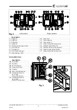
Page 3: ...sor supply air filter 14 Electrical Heater Water coil 6 Fan extract air 15 Electrical Connection box see fig 3 7 Fan supply air 16 Pressure sensor extract air filter 8 Control Heat exchanger 17 Pressu...

Page 4: ...r extract air accessories 2 Extract air 7 Damper and motor exhaust air accessories 3 Exhaust air 8 Damper and motor outside air accessories 4 Outside air 9 Sensor supply air 5 VAV pressure transmitter...

Page 5: ...5 Table of contents 5 Declaration of Conformity 6 Electrical connection 7 Description of functions Topvex SR E EL 8 Description of functions Topvex SR E HW 9 Dimension and Weight 10 Transport and sto...

Page 6: ...00 1 Safety of machinery Basic concepts general principles for design Part 1 Basic terminology methodology EN ISO 12100 2 Safety of machinery Basic concepts general principles for design Part 2 Techni...

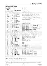
Page 7: ...r 37 G0 Neutral Damper outdoor air Water valve actuator cooling EL units only 38 G 24V AC Damper outdoor air Water valve actuator cooling EL units only 39 DO 24V AC 0 5A Water pump control voltage con...

Page 8: ...amper when the appliance is stopped In case of an unintended stop on the rotor a signal is sent to RC which is displayed on the Control panel as an alarm Also displayed in the Control panel are date a...

Page 9: ...ans have stopped DO closes the outdoor air damper when the appliance stops In case of an unintended stop on the rotor a signal is sent to RC which is displayed on the Control panel as an alarm Also di...

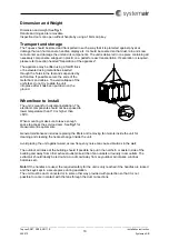
Page 10: ...t do not try to slide the unit into place after it has been put down on the ground Where how to Install The unit is meant for horizontal installation The electronic components should not be exposed to...

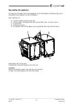
Page 11: ...port to the site of installation How to split the unit A Loosen the cable connectors in the wall B The two halves of the appliance are joined using 4 M10 screws one in each corner C Control section D...

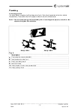
Page 12: ...se have hexagonal connectors internal threaded tube Cover plates around the pipes are fixed to the unit reinforcement Note Take care not to damage the water battery when connecting water pipes to conn...

Page 13: ...n To obtain the heat recovery efficiency it is especially important to insulate the Supply and Extract air ducts against heat losses Use insulating covering minimum 100 mm mineral wool with plastic di...

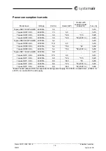
Page 14: ...opvex SR07 E EL 400V3N 3 0 12 0 30 230V 3 3x40 Topvex SR09 E HWL HWH 400V3N 5 4 3x10 Topvex SR09 E EL 400V3N 11 9 4 5 3x16 Topvex SR09 E EL 400V3N 5 4 15 0 22 3x32 Topvex SR09 E EL 400V3N 5 4 15 0 38...

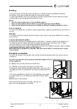
Page 15: ...ly voltage 24V AC Control signal 0 10 V can be connected to the unit and be operated in sequence to the heater battery A DX cooler can be connected to the unit See page 6 to see which terminal blocks...

Page 16: ...If there is still a risk of freezing the unit is stopped and the outdoor sir dampers accessory are closed Control panel The SCP control panel is delivered with a 10m cable that is pre connected to the...

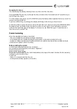
Page 17: ...to a menu or menu item This is indicated by an arrow symbol at the right hand edge of the display To choose one use RIGHT again To back down to a lower menu level use LEFT Commissioning When the insta...

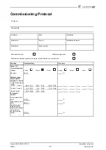
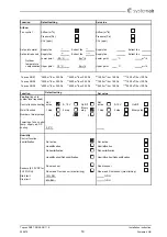
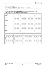
Page 18: ...UIRUPHG XQFWLRQ HIDXOW VHWWLQJ 6HW YDOXH 7HPS RQWURO IXQFWLRQ WHPS 6XSSO WUDFW 5RRP 6XSSO WUDFW 5RRP 6HW SRLQW 2XWGRRU WHPS FRPSHQVDWHG VXSSO DLU FRQWURO 2XWGRRU VXSSO DLU WHPS 3RLQW DQG 3RLQW DQG 3RL...

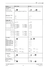
Page 19: ...RU 3D P K RU 3D XQFWLRQ HIDXOW VHWWLQJ 6HW YDOXH RROLQJ ORJRQ WR V VWHP OHYHO UHTXLUHG RQWURO IXQFWLRQ FRROLQJ 1RW DFWLYH 9 2Q 2II 1RW DFWLYH 9 2Q 2II 2Q RII IXQFWLRQ VWHS VWHS LQDU VWHS VWHS VWHS LQ...

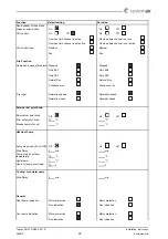
Page 20: ...DQG KROLGD V 3HULRG WR 0RQGD WR 6XQGD DQG SXEOLF KROLGD V WR RII SHULRG 2 6 1RUPDO IDQ VSHHG KDV SULRULW RYHU D UHGXFHG IDQ VSHHG HHNGD 3HULRG 1RUPDO IDQ VSHHG 5HGXFHG IDQ VSHHG 0RQGD 7XHVGD HGQHVGD 7...

Page 21: ...WHPSHUDWXUHV KLJKHU WKDQ 6WRSSHG DW RXWGRRU QLJKW WHPSHUDWXUHV KLJKHU WKDQ 6WRSSHG DW RXWGRRU QLJKW WHPSHUDWXUHV ORZHU WKDQ 6WRSSHG DW URRP WHPSHUDWXUHV ORZHU WKDQ RXU IRU VWDUW VWRS 6WDUW 6WRS 6WDUW...

Page 22: ...QWLQXRXV UXQ LUH QSXW 1RUPDOO RSHQHG 1RUPDOO RSHQHG 1RUPDOO FORVHG 1RUPDOO FORVHG WHUQDO 6HW SRLQW QRE WHUQDO VHW SRLQW NQRE 2II 2Q 2II 0LQ VHW SRLQW RI NQRE 0D VHW SRLQW RI NQRE HDW 3XPS 3XPS VWRS PR...

Page 23: ...DUP ODVV 1RW DFWLYH ODVV HOD V HOD V 7KH XQLW VWRSSHG DW DODUP 1R 7KH XQLW VWRSSHG DW DODUP 1R 0DOIXQFWLRQ 3 FRROLQJ ROG ZDWHU SXPS DLOXUH RI DLU VXSSO ODVV 1RW DFWLYH ODVV HOD V HOD PLQ 7KH XQLW VWRS...

Page 24: ...VV 1RW DFWLYH ODVV 1RW DFWLYH HOD V HOD V 7KH XQLW VWRSSHG DW DODUP 1R 7KH XQLW VWRSSHG DW DODUP 1R RZ URRP WHPSHUDWXUH RZ H KDXVW WHPSHUDWXUH ODUP VHWWLQJV HI VHWWLQJ 6HW YDOXH ODUP VHWWLQJV HI VHWWL...

Page 25: ...RW DFWLYH HOD PLQ HOD V 7KH XQLW VWRSSHG DW DODUP HV 7KH XQLW VWRSSHG DW DODUP 1R DUJHVW GLII EHWZHHQ PXVW LV YDOXH 3D ODUP VHWWLQJV HI VHWWLQJ 6HW YDOXH ODUP VHWWLQJV HI VHWWLQJ 6HW YDOXH 0DQXDO KHDW...

Page 26: ..._____________________________________________________________________________________________________ Topvex SR07 SR09 SR11 E Installation instruction 205870 Systemair AB 26 Notes...

Page 27: ......
Page 28: ...ves the right to make changes and improvements to the contents of this manual without prior notice Systemair AB Industriv gen 3 739 30 Skinnskatteberg Phone 46 222 440 00 Fax 46 222 440 99 www systema...

Reviews: