43/55 |
S-BA2
Installation D1V
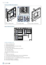
Vertically Oriented Damper, on the Duct
The S-BA2 smoke control damper can be installed on these types of ductwork: - “single” ductwork (the tests refer to
EN 1366-9) - “multi” ductwork (the tests refer to EN 1366-8).
This section does not give information about duct hanger rules. These rules are related to the weight of the duct and
they must have static approval.
Hang the smoke control dampers from solid ceiling slabs with rods that have a thread. The dimension of these rods
must be sufficient for the weight of the damper.
If you use anchors in the ceiling, make sure that you use a fire- rated anchor (with the correct fire rating certificate).
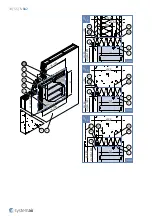
1. Prepare the duct connections:
a. Clean the ductwork connection surfaces.
b. Apply sealant on the ductwork connection surfaces, following ductwork manufacturer instructions.
2. Connect the damper corners to the ductwork flange with screws (F2).
3. Screw self drilling screws (F9) through the ductwork flange and the damper flange with the distance of maximum
150 mm.
4. Insulate the duct and the damper with insulation (F6)
5. Bind the damper insulation with screws for insulation (F8)
6. Bind the damper insulation and the duct insulation with screws for insulation (F8)
7. Cover the mineral wool edges and the mineral wool connections with tape (F7).
8. Perform damper's functionality check (see "Operation Manual" section).
CAUTION:
• Make sure that the damper hanger only holds the weight of the damper.
• If the hanger system is longer than 1,5 m, fire-resistant insulation is necessary.
• The forces from thermal expansion of the duct must be avoided using flexible connections or duct bends.
• Make sure that it is always possible to access the smoke control damper internally for maintenance. If necessary,
make inspection panel in the connecting duct.
• Duct with lower resistivities will decrease the fire resistivity of smoke control damper.
• The maximum fire resistance for in-duct installation is EI120 with pressure level 2 (-1000 Pa … 300 Pa).
Installation Distances
The minimum distance between the damper body and the wall or ceiling must be 75 mm (refer to Standard EN
1366-2). The minimum distance between two damper bodies is 200 mm.
D1V
S-BA2
150 × 250 ...
... 800 × 1000
EI 120 (v
ed
i ↔ o)
S1000 C
MOD
AAmulti
d)
EN 1366-9
EN 1366-8
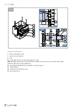
NOTES:
d)
- Duct per EN 1366-9 or EN 1366-8
h
od
- Vertical duct (horizontal damper orientation)


