background image

42/46 | 

FDR-3G…OF

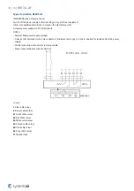
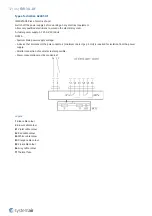
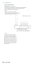
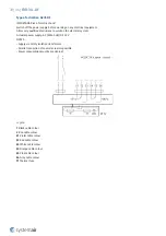
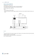
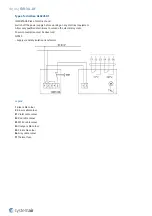
Type of activation BSD24T-OF

IMPORTANT: Risk of electric shock!
Switch off the power supply before working on any electrical equipment.
Allow only qualified electricians to work on the electrical system.
Power consumption must be observed.
NOTES:
• Supply via safety isolation transformer.

Legend

1

 Blue cable colour

2

 Brown cable colour

S1

 Violet cable colour (white for BF24-T)

S2

 Red cable colour (white for BF24-T)

S3

 White cable colour (white for BF24-T)

S4

 Orange cable colour (white for BF24-T)

S5

 Pink cable colour (white for BF24-T)

S6

 Grey cable colour (white for BF24-T)

Tf

 Thermal fuse

Summary of Contents for A-FDR-3G-OF

Page 1: ...FDR 3G OF Overflow Fire Damper FDR 3G...

Page 2: ...2 46 FDR 3G OF Table of Contents Overview 3 Technical Parameters 5 Diagrams 10 Dimensions 11 Ordering Code 12 Installation 14 Electrical parameters 32 Operation manual 44...

Page 3: ...after the melting of the thermal fuse After the closing of the damper blade it is mechanically locked in the closed position and can only be opened manually The actuating mechanism is activated when t...

Page 4: ...C and auxiliary switches BSD230T OF or GSD230T OF Overflow fire damper with Smoke Detector fitted activation mechanism AC 230 V with a Belimo or Gruner spring return actuator with an electro thermal...

Page 5: ...operated 72 C as standard by means of the spring after current interruption in the electro thermal fuse and or after smoke sensor detection Operational temperature Minimum 0 C Maximum 60 C for 74 C an...

Page 6: ...agnetic Compatibility Directive Driving actuator types Belimo BLF230 T BLF24 T BF230 T BF24 T BFN230 T BFN24 T BFN24 T BFL230 T BFL24 T also with connection possibilities with acronyms ST W Gruner 360...

Page 7: ...d activation mechanism H0 H P4 Actuator operated activation mechanism B G P5 Inspection lid P6 Thermoelectric fuse BAT72 TA 72 P7 Supply and communication unit BKN230 24 FS UFC24 2 P8 Bendable hanger...

Page 8: ...8 46 FDR 3G OF P13 Hexagon bent wrench No 10 not part of delivery P14 Smoke detector Hekatron ORS 142 P15 Grid P16 Extended ductwork...

Page 9: ...time Pass closure time Operational reliability Pass motorized cycle 10 200 cycles manual cycle 50 cycles modulated 20 200 cycles Fire resistance Resistivity depending on installation method and situat...

Page 10: ...e 280 Size 315 Size 400 25 dB A 30 dB A 35 dB A 40 dB A 45 dB A 50 dB A 25 dB A 30 dB A 35 dB A 40 dB A 45 dB A 50 dB A 25 dB A 30 dB A 35 dB A 40 dB A 45 dB A 50 dB A FDR 3G H0 OF Pressure drop sound...

Page 11: ...verhangs DN mm 200 225 250 280 315 355 400 450 500 560 630 L1 mm 50 75 L2 mm 50 195 295 Weights m kg 5 DN mm 200 225 250 280 315 355 400 450 500 560 630 H0 OF H2 OF H5 2 OF H6 2 OF 5 1 6 3 7 0 7 7 8 6...

Page 12: ...detector 24 V AC DC 24 V AC DC Belimo Actuator GSD230T OF 230 V AC Supply unit Smoke detector 24 V AC DC 24 V AC DC Gruner Actuator BSD24T OF Smoke detector 24 V AC DC 24 V AC DC Belimo Actuator GSD24...

Page 13: ...13 46 FDR 3G OF 250 DN 630 Standardardly in position B On demand in position L T...

Page 14: ...ds and mineral wool filing 3 Soft Soft Installation using mineral wool filing 3H Hilti Filling made only from Hilti foam a Flexible plasterboard wall b Concrete masonry cellular concrete rigid wall ve...

Page 15: ...ulted resistivity is reduced to EI90S The distance between the wall ceiling and the fire damper must be at least 75 mm This condition does not apply for tested distances Therefore Wet and Soft install...

Page 16: ...onality Installation Standard Distances According to the standard EN 1366 2 the minimum distance from the wall or ceiling to the damper body is 75 mm For multiple crossings through a fire resistive wa...

Page 17: ...17 46 FDR 3G OF...

Page 18: ...18 46 FDR 3G OF...

Page 19: ...es 4d Mineral wool thickness cubic density see picture 5 Flexible wood beam wall 5a Vertical spruce wooden beam 60 100 mm 5b Horizontal spruce wooden beam 80 100 mm 6 Alternative thinner wall classifi...

Page 20: ...FD cover boards for a rectangular damper use CBS FD cover boards with screws F1 through pre drilled holes 5 All the gaps between the cover boards between cover boards and the wall and between cover b...

Page 21: ...21 46 FDR 3G OF...

Page 22: ...22 46 FDR 3G OF...

Page 23: ...rd fireproof plate type F EN 520 4b Vertical CW profiles 4c Horizontal CW profiles 4d Mineral wool thickness cubic density see picture 5 Flexible wood beam wall 5a Vertical spruce wooden beam 60 100 m...

Page 24: ...on the exposed filling and wall edges evenly from both sides Do not apply this layer in the place where the mechanism is located inspection openings and manufacturer labels 5 If needed uncover and cl...

Page 25: ...25 46 FDR 3G OF...

Page 26: ...26 46 FDR 3G OF...

Page 27: ...rboard fireproof plate type F EN 520 4b Vertical CW profiles 4c Horizontal CW profiles 4d Mineral wool thickness cubic density see picture 5 Flexible wood beam wall 5a Vertical spruce wooden beam 60 1...

Page 28: ...per s functionality Installation Standard Distances According to the standard EN 1366 2 the minimum distance from the wall or ceiling to the damper body is 75 mm For multiple crossings through a fire...

Page 29: ...29 46 FDR 3G OF...

Page 30: ...30 46 FDR 3G OF...

Page 31: ...zontal CW profiles 4d Mineral wool thickness cubic density see picture 5 Flexible wood beam wall 5a Vertical spruce wooden beam 60 100 mm 5b Horizontal spruce wooden beam 80 100 mm 6 Alternative thinn...

Page 32: ...BFN24 T ORS144K T PC A DN mm 200 225 250 280 315 355 400 450 500 560 630 G230T OF 9 5 VA 340TA 230 05 G24T OF 9 VA 340TA 024 05 G24T W OF 9 VA 340TA 024 05 ST01 GSD230T OF 11 VA 340TA 024 05 ST01 BKN...

Page 33: ...to work on the electrical system Microswitch Power Supply AC 125 250 V or DC 12 24 V Electric Parameters 3A NOTES Supply via safety isolation transformer Legend 1 Grey cable colour 2 Orange cable colo...

Page 34: ...24 V Electric Parameters 3A Impulse Electromagnet Power Supply AC 50 60 Hz DC 24 V Electric Parameters 50 VA load factor 10 maximum 30 seconds in operation NOTES 50 VA Nominal activation power maximu...

Page 35: ...Supply AC 230 V 50 60 Hz Electric Parameters 50 VA load factor 10 maximum 30 seconds in operation NOTES 50 VA Nominal activation power maximum permissible magnet load 300 VA Caution Main power supply...

Page 36: ...0 60 Hz NOTES Caution Main power supply voltage A device that disconnects the pole conductors minimum contact gap 3 mm is required for isolation from the power supply Parallel connection of several ac...

Page 37: ...0 60 Hz NOTES Caution Main power supply voltage A device that disconnects the pole conductors minimum contact gap 3 mm is required for isolation from the power supply Parallel connection of several ac...

Page 38: ...TES Supply via safety isolation transformer Parallel connection of several actuators possible Power consumption must be monitored Legend 1 Blue cable colour black for BF24 T 2 Red cable colour white f...

Page 39: ...n the electrical system Actuator power supply AC 50 60 Hz DC 24 V NOTES Supply via safety isolation transformer Parallel connection of several actuators possible Power consumption must be monitored Le...

Page 40: ...must be observed NOTES Caution Main power supply voltage A device that disconnects the pole conductors minimum contact gap 3 mm is required for isolation from the power supply Legend 1 Jumper factory...

Page 41: ...must be observed NOTES Caution Main power supply voltage A device that disconnects the pole conductors minimum contact gap 3 mm is required for isolation from the power supply Legend 1 Jumper factory...

Page 42: ...e electrical system Power consumption must be observed NOTES Supply via safety isolation transformer Legend 1 Blue cable colour 2 Brown cable colour S1 Violet cable colour white for BF24 T S2 Red cabl...

Page 43: ...ent Allow only qualified electricians to work on the electrical system Power consumption must be observed NOTES Supply via safety isolation transformer Legend 1 Blue cable colour 2 Brown cable colour...

Page 44: ...he operating position Smoke detector and spring return actuator operated activation mechanism 1 The fire damper must open automatically after the actuator circuit closes the arrow on the actuator axis...

Page 45: ...ection The removable mechanism always needs to be returned back into the damper with the damper blade being closed The damper s internal casing thermal fuse sealings foaming substance the damper blade...

Page 46: ...Systemair DESIGN 2021 04 27 Handbook_FDR_3G_OF_en GB...

Reviews: