page
5
I
ndustrIal
pC - COpIlOt 15"
O
rder
C
Ode
190331
xxxx
M
ay
2009 - r
ev
. 1.5
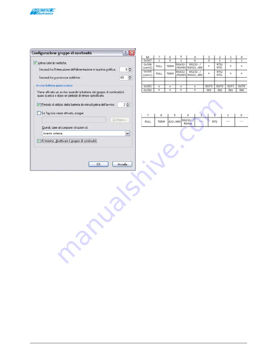
It is recommended to keep the UPS management
settings as shown below (2 minutes of normal use of
the terminal before the automatic "soft" shutdown of
the applications).
System suspension and shutdown can be configured
following a power cut.
Figure 3.5.1
3.6 Connectivity
The Wireless solutions of the COPILOT allow maximum
freedom and flexibility of use and allow remote
equipment to be piloted.
The COPILOT is a universal operator interface, for the
possibility to communicate with the machine and receive
the required data only, as well as the desired manuals
and easily manage the update of the equipment.
Native interfaces:
•
2 USB connectors on the rear side.
•
Ethernet 10/100.
•
MiniPCI Wi-Fi: wireless radio communication
according to Standard 802.11b/g at 2.4GHz, with
point-to-point access or an access point. Possibility
of encrypting the data for increased WEP security
at 64 or 128 bit. The maximum distance between
two communicating units or between the COPILOT
15" and the access point is 100 m.
Two internal antennas or one external antenna can
be installed for applications that require maximum
performance and radio coverage.
The FULL version of the COPILOT 15" allows the full
capacity of the terminal to be used for OEM applications
of other services:
•
Two PC104+ slots (for high performance boards
on PCI/ISA bus) allow other boards to be used for
custom applications (CAN, GPS, camera, GPRS,
modem, additional Ethernet, etc.).
•
Connection for additional ethernet 10/100 Mbit
with chipset i82551er.
•
The optional TV output and audio (Audio LineIN,
Mic, LineOut) can be requested for multimedia
applications.
•
There are 4x24V inputs and 4x24V outputs 250mA
max non-isolated, protected against short circuits.
Table 3.6.1
Configuration of the serial ports: (Com1 and Com2).
Table 3.6.2
Bit2: RTS/RTS-: Selects how to enable the driver in
transmission for RS422 and RS485 protocols.
(RTS-) 0: normally not in transmission:
controlled by the RTS signal.
(RTS) 1: normally in transmission: controlled by
the RTS signal.
Set bit 2 to '1' to use the RS422 serial port as a
point-to-point always in transmit/receive.
Bit4: selects between RS232 and 422/485.
0 must be written on the bit to use the serial
ports as RS232: and 422/485 is selected by
setting the value to 1.
Bit5: selects between RS422 and RS485 (half duplex
or full-duplex).
This bit bears no significance for the RS232
mode. (set to 0). 0 must be written on the bit
to use the serial ports as RS422: and RS485 is
selected by setting the value to 1.
Bit6: termination of the TX+/TX- and RX+/RX- lines.
This bit is to be set to 0 for the RS232 mode.
1 must be written on the bit to terminate the
lines. 120 ohm termination.
Bit7: PullUp and PullDown of the TX+/TX- and RX-
/RX lines. This bit is to be set to 0 for the
RS232 mode. 1 must be written on the bit to
insert the pull-ups on the TX+ and RX+ and
the pull-downs on the TX- RX- lines. 470Ω
resistors b5V and towards the GND,
respectively.
RS232: 0x00
RS422 Multidrop: 0xD0
RS485: 0xF0
RS422 Point-to-Point: 0xD4
The inputs are mapped in I/O at the 0x300 address.
The outputs are mapped in I/O at the 0x301 address.
The HW release can be read at the 0x307 address: 0xA7
or 0xA5 for the ultra light version.


