4.3 Mounting the device
The device is kept cool by means of the vents on the back.
Make sure that the installation process does not obscure
these and prevent air from circulating.
You must ensure that the switch cabinet or rack wall allows
for a sufficient volume of air.
1.
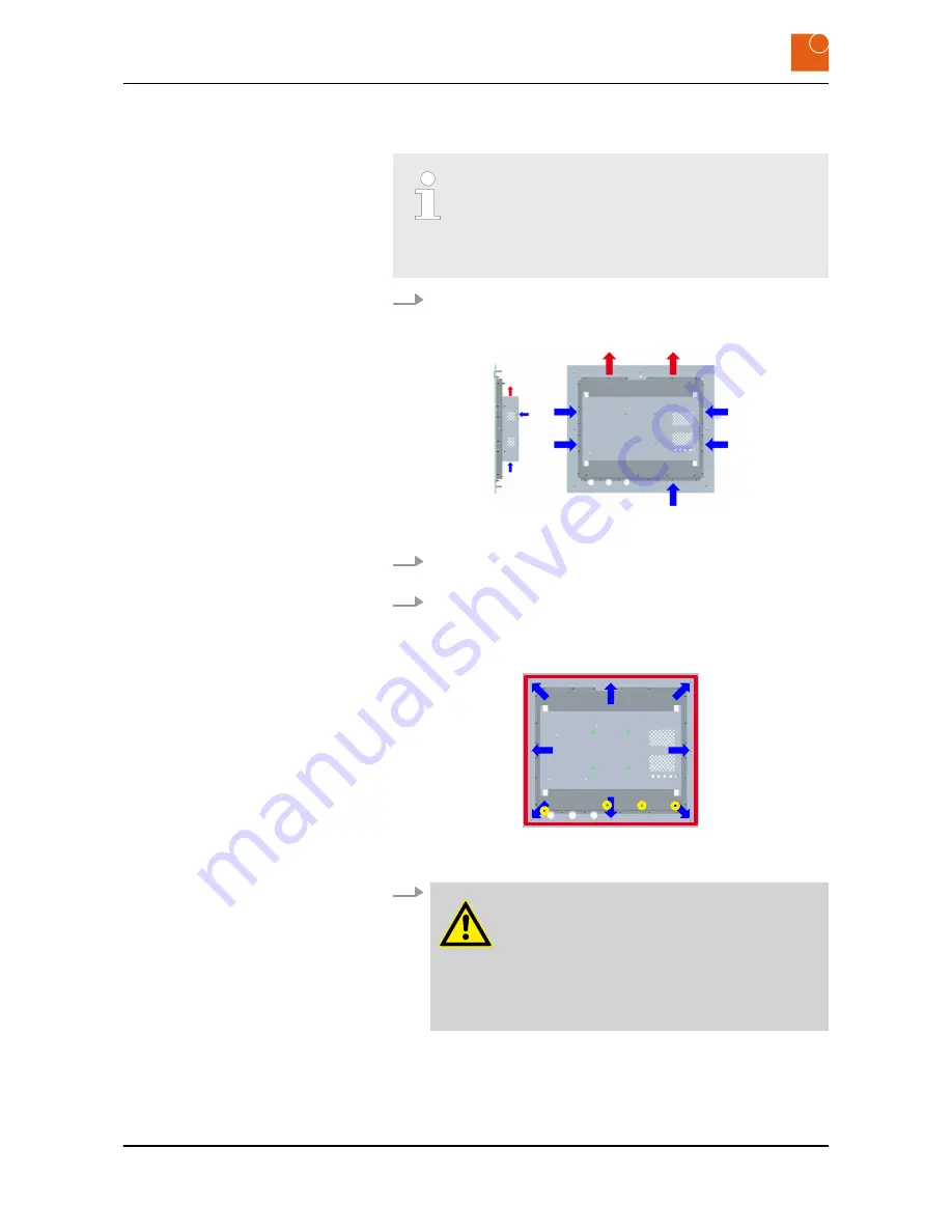
Make sure that the device is mounted in such a way that there is
at least 50 mm of free space all around it and at least 20 mm at
the back.
Fig. 19: Diagram showing cold (blue) and hot (red) ventilation airstreams
2.
If the device is enclosed you should arrange for suitable ventila-
tion (see the illustration).
3.
The enclosed wall template shows the size of the necessary
cutout and the drilling holes.
You will find an image of the wall template in section
Ä
Chapter 3.4 “Dimensions” on page 15
.
Fig. 20: Rear view showing sealing tape (red), M6 threaded bolts (blue) and
M3 threaded bolts (yellow)
4.
WARNING!
Danger of injury due to excessive load.
Working on heavy equipment may lead to serious
injuries.
– Always have two people when working with
heavy equipment.
Push the device into the installation cutout from the front and
hold it firmly in place.
Starting up
Mounting the device
CONTROL 217 PC - Industrial PC
24
Summary of Contents for CONTROL 217 PC
Page 4: ...Table of contents CONTROL 217 PC Industrial PC 4 ...
Page 6: ...General information Copyright notice CONTROL 217 PC Industrial PC 6 ...
Page 10: ...Safety Important safety notes CONTROL 217 PC Industrial PC 10 ...
Page 22: ...Product description Conformity CONTROL 217 PC Industrial PC 22 ...
Page 26: ...Starting up Mounting the device CONTROL 217 PC Industrial PC 26 ...
Page 34: ...Repairs CONTROL 217 PC Industrial PC 34 ...
Page 38: ...Packaging and transport Transporting the device CONTROL 217 PC Industrial PC 38 ...


