Syntec 610-E5 Operation Manual Download Page 89

机床产品

/Machine Tool Products

                             – 

                            610-E5/610-H5 5-Axis Wood Operation Manual

Machine Operation Panel

                             – 

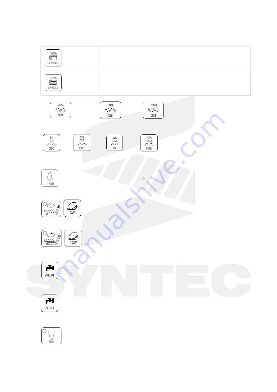
Spindle rate 100%: Spindle will rotate with 100% speed.

Spindle rate acceleration: Spindle speed will accelerate by 10%.

G01 Segments


Decrease G01 rate by 10%    Increase G01 rate by 10%     G01 rate 100%

G00 Segments


G00 rate x1       G00 rate x10       G00 rate x100        G00 rate x1000

Those function key can be regard as G00, MPG or INJOG segments.

Working LED

Working LED On/Off

Chip Conveyor Machine Clockwise Rotation


Switch chip conveyor machine to clockwise rotation

Chip Conveyor Machine Counterclockwise Rotation


Switch chip conveyor machine to counterclockwise rotation

Cutting Fluid

Working liquid On/Off

Auto Cutting Fluid

The cutting fluid M code of machining program will only be enabled after applying this function.

Blowing

Summary of Contents for 610-E5

Page 1: ...610 E5 610 H5 5 Axis Wood Operation Manual 2022 03 09 2020 03 23...

Page 2: ...h Simulation File Manager Offset Setting Workpiece Cord Tool Set Tool Tip Measure User Parameter Setting Monitor Monitor Area of Machining Information Open File to Edit Simulation Switch MDI Input Par...

Page 3: ...ation Manual Function Machining Process Workpiece Preparation Workpiece Cord set Middle Func Tool Prepare Program Preparation and Execute Machining Select Machining Program Machining Test Machining Mo...

Page 4: ...j k 1 Function Key and System Configuration 1 1 Main Screen Sections Meanings for Sections on the Display Present coordinate system Working file name and machining command line Title of interface Cur...

Page 5: ...Machine Tool Products 610 E5 610 H5 5 Axis Wood Operation Manual Function Key and System Configuration 5 Key System 10 8 key system...

Page 6: ...nfiguration 1 3 Coordinate Command F1 Coordinate Function Switch current coordinate system on the screen Display the frequently use machining information Use the function key POS can switch to the cur...

Page 7: ...indle User input Spindle speed RPM Actual speed of spindle mm min Percentages of Spindle speed Run Time Machining Duration Part counter Number of parts that had been finished T Tool No Current Tool no...

Page 8: ...Zero Rel Coord Function Set the Relative Coordinate to zero Operation Method Key in the axis that you want to calculate and then press Zero Rel Coord Example Current Rel Coord of X axis is 10 000 Key...

Page 9: ...een for editing purpose With Page Up Page Down to switch the pages With Home End can let the cursor jump between the top and end of the line With the function key Prog File can quickly switch between...

Page 10: ...text Operation Method Press Search Replace function key then Replace box will appear just enter the text that you want to search and replace for Find Next Command F2 Program F3 Search Replace F1 Find...

Page 11: ...tting Function Reset Search Replace string Operation Method Press F4 Modify Setting to reset the Search Replace content 1 4 4 Can Cycle Command 5 Buttons type F2 Program Next F1 Can Cycle 8 Buttons ty...

Page 12: ...press OK the desired G code will insert into the next line of current cursor Edit Cycle Command 5 buttons type F2 Program Next F1 Can Cycle F2 Edit Cycle 8 buttons type F2 Program F4 Can Cycle F2 Edi...

Page 13: ...ock Copy F4 Block Copy 8 Buttons F2 Program F5Block Copy F4 Block Copy Function Copy the block that had been selected Block Paste Command 5 Buttons F2 Program Next F2 Block Copy F5 Block Paste 8 Butto...

Page 14: ...y can be pasted for many times 1 4 6 Teach Command 5 Buttons type F2 Program Next F3 Teach 8 Buttons type F2 Program F6 Teach Function Move the machine table with MPG JOG INJOG to the destination and...

Page 15: ...as the arc center Move the worktable to the ending of the arc and press Arc Cut Teach current absolute coordinate will be define as the ending of the arc Controller will automatically calculate the re...

Page 16: ...apability of debug Default display range will be the span of the full program Simulation setting can be modified by F5 simulate Setting Step Command 5 Buttons type F2 Program F5 Simulation F1 Step 8 B...

Page 17: ...ulation window Operation Method Press F3 Zoom there will be a block show up Use can move the window up down left and right Use Page Up Page Down to change the zooming area Press ENTER to check the res...

Page 18: ...mulate plane Quadrant can define are as below First Second Third Fourth Simulate Mode Setting profile simulate method Simulation When user go to the Monitor page simulation will show up automatically...

Page 19: ...e can be setting with Pr3213 Operation Method Use on the key pad to move the cursor to anywhere on the screen for editing purpose With Page Up Page Down to switch the cursor between pages Press ENTER...

Page 20: ...NC as well The length of file name cannot be longer than 32 characters include file extension Delete File Command 5 Buttons type F2 Program F4 File Manager F3 Delete File 8 Buttons type F2 Program F8...

Page 21: ...Buttons type F2 Program F4 File Manager F4 File Transfer F2 File Export 8 Buttons type F2 Program F8 File Manager F4 File Transfer F2 File Export Function Export file within controller to outer device...

Page 22: ...rnal devices such as USB Network Operation Method Use to select file and then press Confirm the selected file to be executed Title of selected file will be showed DNC file name Note Valid from 6MDs 6s...

Page 23: ...Use PageUp PageDown to switch between pages Note After setting the workpiece coordinate please set the tool length compensation again Modification Timing External Shift Able to modify Block stop ex M0...

Page 24: ...et Setting F1 Workpiece Coord F2 Rel Coord Teach 10 8 key G3 Offset Setting F1 Workpiece Coord F2 Rel Coord Teach Explanation Set current cursor located workpiece coordinate value into the correspondi...

Page 25: ...ess Inc Input The workpiece coordinate value will then become the value of cursor located coordinate value keyed in teaching value Example Current G54 X axis value is 5 000 Move cursor to the G54 X ax...

Page 26: ...ove the tool with MPG reach Py1 point in the figure and press Py1 Set The current location will be set as the machine coordinate of Py1 and be recorded on the screen The machine coordinate of workpiec...

Page 27: ...near the center point distance between the tool and the upper surface should allow the tool to move freely and not touching the surface The point will be the starting point of auto middle function Swi...

Page 28: ...r versions before 10 116 36D Parameter Explanation Diameter Geometry G41 G42 Cutter radius Dn compensation please input radius not diameter Diameter Wear Minor modification of cutter radius Length Geo...

Page 29: ...axis machine coordinate value valid version from 2 2 0 Press F3 Set Tool Rel Coord the tool length compensation value of where the cursor is located will be set as current Z axis relative coordinate v...

Page 30: ...same time The displayed axes must meet the following three conditions at the same time Must be Z axis Must be a linear axis The axis must be visible not hidden Provides 96 sets of tool setups Operatio...

Page 31: ...relative coordinate value Tool No Path F3 Offset Setting F2 Tool Set F7 Tool No Function Please refer to chapter 3 4 4 for details Tool Life Manag Path 10 8 key Right column Offset Set F2 Tool Set F8...

Page 32: ...r details 1 6 Monitor Path 5 key 8 key F4 Monitor 10 8 key G4 Monitor Function This fenubar group provides the necessary information which needs to be monitored during machining process Fenubar Introd...

Page 33: ...ng to the number of supporting axes support more than 6 axes F5 Tool Wear Set Function Show the tool wear set screen ARM machine Tool Wear Set and Information are at the same fenubar layer the tool we...

Page 34: ...Function Clear the accumulated machining time to zero 10 8 key File Manager Function F9 5 key 8 key N A Function N A 10 8 key Work Record Function Show the work record F10 5 key 8 key N A Function N A...

Page 35: ...ally If you want to do the initialization by manual press Parameter Set switch to Part count set the Total Acum Par as 0 Part Count Part Count Count no will begin from zero when the program is running...

Page 36: ...and run time will be reset to 0 When required part number is reached system will change to halt status Required part Set the upper limit of part count number Once part count number is reached an alarm...

Page 37: ...lanation Switch the screen between Machining Parameter and Machining Information 1 6 6 Tool Wear Set Path 5 key 8 key F4 Monitor F5 Tool Wear Set 10 8 key G4 Monitor F5 Tool Wear Set Description Set t...

Page 38: ...tings and controller software information 1 7 1 Alarm Path 5 key 8 key F5 Maintain F1 Alarm 10 8 key G5 Maintain F1 Alarm Explanation Display alarm messages on the screen Pending Alarm Path 5 key 8 ke...

Page 39: ...lt name of the exported files Pending Alarm Actalm txt History Alarm Histalm txt Alarm Analysis Available versions 10 118 42S 10 118 48D 10 118 50 and above Descriptions Alarm Analysis page has two pa...

Page 40: ...y list focus to refresh right side detail records Use F9 F12 to view help of the alarm Use right left key to switch focus between Alarm category list and Alarm detail list Analyze All Path 5 key 8 key...

Page 41: ...can then be skipped IP Address Enter the applicable IP address in the domain Subnet Mask Enter the subnet mask of the IP address Should be the same as the setting at PC end PC Name Name of the connec...

Page 42: ...Server F3 CloudAgent Setting 10 8 key G5 Maintain F2 Set Kernel Server F3 CloudAgent Setting Explanation Set up the parameters of ProduceCloud and ServiceCloud Require at least 30MB of memory space t...

Page 43: ...to Set Kernel Server F3 ProduceCloud Setting Switch screen to ProduceCloud Setting F4 ServiceCloud Setting Switch screen to ServiceCloud Setting OPCUA Server Path 5 key F5 Maintain F2 Set Kernel Serve...

Page 44: ...Turn On When Power On Yes No Default Setting is No If choose Yes it will start up when power on Description of fenu button F1 Save Setting Save setting and return to Set Kernel Server F2 Cancel Cancel...

Page 45: ...on Manual Function Key and System Configuration System Data Path 5 key 8 key F5 Maintain F3 Fast Diagnosis F1 System Data 10 8 key G5 Maintain F3 Fast Diagnosis F1 System Data Explanation Display basi...

Page 46: ...ion Syntec controllers provide R81 R100 total 20 registers for machinery to use each register can be divided into 16 Bits With the 20 register sets machinery can provide users the control flag of spec...

Page 47: ...intain F5 Sys Setting Explanation This page is used for system environment setting Operation Method Move the cursor with Switch pages with PageUp PageDown Input Display Unit Explanation Set the unit o...

Page 48: ...ges with PageUp PageDown Set Default Path 5 key 8 key F5 Maintain F5 Sys Setting F8 Set MMIConfig F4 Set Default 10 8 key G5 Maintain F5 Sys Setting F8 Set MMIConfig F4 Set Default Explanation Reset t...

Page 49: ...6 F7 F8 My Favor 10 8 key G5 Maintain F5 Sys Setting F8 Set MMIConfig F6 F7 F8 My Favor Explanation For 8 key system of ARM controller provides user define function to F6 F7 F8 of first fenubar layer...

Page 50: ...ys 10 8 key F5 Maintain F6 Backup Sys Explanation Backup system data as a compressed file and saved into the assigned external device Online Backup Path 5 key F5 Maintain Next F1 Backup Sys F5 Online...

Page 51: ...Tool Products 610 E5 610 H5 5 Axis Wood Operation Manual Function Key and System Configuration 1 7 7 System Permissions Path 5 keys F5 Maintain Next F3 Use Time Setting 8 key F5 Maintain F8 Use Time...

Page 52: ...etting F10 Require a license to use Explanation This fenu button will only be displayed when CNC has an authorization term and connects to cloud service successfully Press this fenu button to apply to...

Page 53: ...user s access to each function Please refer to Account Management Application Manual for further details Change Password Path 5 key F5 Maintain Next Next F4 Authority Management F1 Change Password 8...

Page 54: ...on Can be used to reset the password of the machinery 1 7 13 About Path 5 key F5 Maintain Next Next Next F5 About 8 key F5 Maintain Next F8 About 10 8 key G8 System F10 About Explanation Provide syste...

Page 55: ...Key and System Configuration Normal Axis Information Normal Axis Path 5 key F5 Maintain Next Next Next F5 About F2 Normal Axis Information F1 Normal Axis 8 key F5 Maintain Next F8 About F2 Normal Axis...

Page 56: ...stem Configuration Displays invalid content as N A SPLCA Path 5 key F5 Maintain Next Next Next F5 About F2 Normal Axis Information F2 SPLCA 8 key F5 Maintain Next F8 About F2 Normal Axis Information F...

Page 57: ...key F5 Maintain Next F8 About F2 Normal Axis Information F3 ROT Explanation Display information of ROT axis Displays invalid content as N A ATC Support from 10 118 22 Path 5 key F5 Maintain Next Next...

Page 58: ...ual Function Key and System Configuration Spindle Information Path 5 key F5 Maintain Next Next Next F5 About F3 Spindle Information 8 key F5 Maintain Next F8 About F3 Spindle Information Explanation D...

Page 59: ...ut F4 Fitting Information F1 Driver 8 key F5 Maintain Next F8 About F4 Fitting Information F1 Driver Explanation Display information of driver fittings Displays invalid content as N A SRI Path 5 key F...

Page 60: ...ne Builder Information 8 key F5 Maintain Next F8 About F5 Machine Builder Information F1 Machine Builder Information 10 8 key G8 System F10 About F5 Machine Builder Information F1 Machine Builder Info...

Page 61: ...ormation All users are permitted to edit machine builder information after logged in the cursor will appear when entering this page If the authority of editing needs to be limited please switch to Aut...

Page 62: ...in Next Next Next F5 About F5 Machine Builder Information F2 Product Registration 8 key F5 Maintain Next F8 About F5 Machine Builder Information F2 Product Registration 110 8 key G8 System F10 About F...

Page 63: ...ter the page and wait for the controller to create 2D bar code Use APP to scan 2D bar code and register the products If there are multiple 2D barcodes the barcode can be switched by function keys Next...

Page 64: ...ation F3 Delivery Backup 8 key F5 Maintain Next F8 About F5 Machine Builder Information F3 Delivery Backup 110 8 key G8 System F10 About F5 Machine Builder Information F3 Delivery Backup Explanation P...

Page 65: ...ducts 610 E5 610 H5 5 Axis Wood Operation Manual Function Key and System Configuration Online Service Path 5 key F5 Maintain Next Next Next F5 About F6 Online Service 8 key F5 Maintain Next F8 About F...

Page 66: ...ormation CPU board type image file version software version Machine Builder Information What you can see in Machine Builder Information Screen Axis Information Yaskawa YAS drive model motor model SYNT...

Page 67: ...Add SYNTEC Wechat official account can be skipped if you already have our official account Wait for 2D bar code Scan 2D bar code Please select via Wechat APP Press OK and the scan box of Wechat will a...

Page 68: ...Wood Operation Manual Function Key and System Configuration 3 4 Fill in the required information Press Save to send the information and press Finish to leave the screen on the controller For Common u...

Page 69: ...repare an app with 2D bar code scanning function The apps showed on the controller screen are recommended Scan 2D bar code and the controller information will be uploaded to the customer service reque...

Page 70: ...F5 Maintain Next Next Next F5 About F4 System Permissions F2 Option Setting 8 key F5 Maintain Next F8 About F7 System Permissions F2 Option Setting 10 8 key G8 System F10 About F4 System Permissions F...

Page 71: ...118 29Z 10 118 40F 10 118 44 included SynFactory Device Binding Path 5 key F5 Maintain Next Next Next F5 About Next F3 SynFactory Binding 8 key F5 Maintain Next F8 About F8 SynFactory Binding 10 8 ke...

Page 72: ...alarm messages on the screen Pending Alarm Path 5 key 8 key F5 Maintain F1 Alarm F1 Pending Alarm 10 8 key G5 Maintain F1 Alarm F1 Pending Alarm Explanation Display current system alarm Up to 20 alarm...

Page 73: ...creen to external device Ex the screen is showing Pending Alarm the contents of current alarm can be exported to external device with this function Default name of the exported files Pending Alarm Act...

Page 74: ...ormations Operations Use up down key to move focus Use PageUp Down key to switch pages Change Alarm category list focus to refresh right side detail records Use F9 F12 to view help of the alarm Use ri...

Page 75: ...HCP when using a normal cable IP Address and Subnet Mask can then be skipped IP Address Enter the applicable IP address in the domain Subnet Mask Enter the subnet mask of the IP address Should be the...

Page 76: ...5 Maintain F2 Set Kernel Server F5 Set Kernel Server F1 Start Server Explanation Start the kernel server immediately CloudAgent Setting Path 5 key F5 Maintain F2 Set Kernel Server F3 CloudAgent Settin...

Page 77: ...cription of fenu button F1 Save Setting Save setting and return to Set Kernel Server The changes of produce cloud and service cloud need to be saved separately F2 Cancel Cancel and return to Set Kerne...

Page 78: ...urn On When Power On Yes No Default Setting is No If choose Yes it will start up when power on Description of fenu button F1 Save Setting Save setting and return to Set Kernel Server F2 Cancel Cancel...

Page 79: ...on Manual Function Key and System Configuration System Data Path 5 key 8 key F5 Maintain F3 Fast Diagnosis F1 System Data 10 8 key G5 Maintain F3 Fast Diagnosis F1 System Data Explanation Display basi...

Page 80: ...ation Syntec controllers provide R81 R100 total 20 registers for machinery to use each register can be divided into 16 Bits With the 20 register sets machinery can provide users the control flag of sp...

Page 81: ...aintain F5 Sys Setting Explanation This page is used for system environment setting Operation Method Move the cursor with Switch pages with PageUp PageDown Input Display Unit Explanation Set the unit...

Page 82: ...ges with PageUp PageDown Set Default Path 5 key 8 key F5 Maintain F5 Sys Setting F8 Set MMIConfig F4 Set Default 10 8 key G5 Maintain F5 Sys Setting F8 Set MMIConfig F4 Set Default Explanation Reset t...

Page 83: ...6 F7 F8 My Favor 10 8 key G5 Maintain F5 Sys Setting F8 Set MMIConfig F6 F7 F8 My Favor Explanation For 8 key system of ARM controller provides user define function to F6 F7 F8 of first fenubar layer...

Page 84: ...ys 10 8 key F5 Maintain F6 Backup Sys Explanation Backup system data as a compressed file and saved into the assigned external device Online Backup Path 5 key F5 Maintain Next F1 Backup Sys F5 Online...

Page 85: ...Machine Tool Products 610 E5 610 H5 5 Axis Wood Operation Manual Function Key and System Configuration 1 7 20 About Command F8 Maintain F8 About Function...

Page 86: ...Machine Tool Products 610 E5 610 H5 5 Axis Wood Operation Manual Function Key and System Configuration Provide controller software version...

Page 87: ...achining fluid will be also cut off to ensure the safety of operator and machine Home Mode When CNC power is on please apply home searching function in home mode JOG Mode Rapid JOG Operators are able...

Page 88: ...finishing one block Operators need to press Cycle Start to move on to the next block This function is normally used to check NC files Optional Stop Operators are able to decide whether to stop or not...

Page 89: ...te x1 G00 rate x10 G00 rate x100 G00 rate x1000 Those function key can be regard as G00 MPG or INJOG segments Working LED Working LED On Off Chip Conveyor Machine Clockwise Rotation Switch chip convey...

Page 90: ...Control the axis movements able to fast travel when pressing the rapid button with arrow keys at the same time 2 2 Keyboard Description Position keys total 26 English character keys used for command p...

Page 91: ...sed to input current data Provide function guide message on screen after pressing Used for optional skip blocks while editing programs Used to represent the end of block in programs Used for decimal f...

Page 92: ...ducts 610 E5 610 H5 5 Axis Wood Operation Manual Machine Operation Panel Used to delete characters while editing programs PAGE UP PAGE DOWN All above symbols are for Program Edit mode Page Up Page Dow...

Page 93: ...Conditions Emergency stop button is released and no alarm exists system will switch state from Not Ready to Ready Under Busy FeedHold B stop state if user presses Reset system will switch to Ready sta...

Page 94: ...s direction key to keep the axis moving uninterrupted JOG speed can be adjusted by G01 Rapid JOG Function Control axis movement toward the selected direction with G00 speed Can control more than one a...

Page 95: ...se generator for the direction to move Turn the dial on manual pulse generator clockwise counterclockwise for forward reverse direction The moving distance when turning one track in MPG mode can be se...

Page 96: ...HOME mode Press axis direction key X X Y Y Z each axis would start HOMING Home direction is defaulted in the CNC parameter Home function can run 3 axes at the same time After HOMING all machine coordi...

Page 97: ...r of workpiece as the starting point of machining Thus the function requires to reach and contact the workpiece edge with detector or tool for the coordinate of workpiece edge the controller will then...

Page 98: ...hown on the screen It s the middle function result calculated by the controller For Auxiliary Coordinate in the bottom right corner the X Y coordinate will now be the value of Pxm and Pym Move the cur...

Page 99: ...machine coordinate into the Px2 and Py2 columns on the screen Move the detector or tool to any point not the same point as P1 or P2 on the circumference of round workpiece point P3 in Fig C Press Set...

Page 100: ...h the page Key in method Absolute Increment Measure method Absolute for radius and length compensate Increment for radius wear and length wear Radius compensate radius wear real G41 G42 compensate Len...

Page 101: ...on Measuring different tool No tip position Because the trigger position of tool alignment equipment is fixed user can use different tool tip position key in the workpiece coordinate system for the re...

Page 102: ...While setting the XY Ref Coord Teach you will need code 520 enter it and choose yes These vaules will be entered in to Ref coord X and Ref coord Y Move the cursor to Start Coord Z setting the start po...

Page 103: ...sert the current Z coord value into Start Coord Z Move the cursor to the Min Z Mach H setting the minimum height for the alignment System will pop out warning message and stop if the tool is lower tha...

Page 104: ...Start Coord Z Move the cursor to the Min Z Mach H setting the minimum height for the alignment System will pop out warning message and stop if the tool is lower than it Please switch to auto mode afte...

Page 105: ...case No 5 This table will renew during change a new tool Time to Modify First initialized when it is made from factory Need to confirm the MG No and T No Manually when it is disordered Tool Manager F...

Page 106: ...tool and use the second one when the second one is lock or Tool life is end will use the third one and so on Tool information Status L Lock U Unlock If the status of tool is lock that tool cann t be...

Page 107: ...nated as the machining program Confirmation There are two ways to confirm whether machining program is specified successfully The screen displays the correct machining program name The content of mach...

Page 108: ...o methods No Cycle Start After activate MPG function the G01 percentage in Monitor page is zero nonzero while user does not does turning MPG dial Already Cycle Start After activate MPG function machin...

Page 109: ...for MDI or Auto mode Able to be operated when the machine is locked Dismiss timing Save the MPG shift coordinate when power on Skip clear after changing the coordinate G54 G55 Skip clear while changi...

Page 110: ...t the time of changing machining files At the moment of modifying the required part count which must be smaller than the part count 3 4 5 Alarm Processing To avoid wrong operation causes danger to hum...

Page 111: ...sharing folder User Name Enter GUEST Press F1 OK and then reboot controller to finish installation 3 4 7 PC Setting XP OS Guest account setting Log in as an Administrator and select start control pane...

Page 112: ...ol Products 610 E5 610 H5 5 Axis Wood Operation Manual How to Operate 21 Series Controller 3 Click OK to confirm sharing setting Select Share this folder on the network and Allow network users to chan...

Page 113: ...Axis Wood Operation Manual How to Operate 21 Series Controller 4 Setting PC name and workgroup Start control panel System change to set Computer Name and Workgroup and remember these setting contents...

Page 114: ...r 5 TCP IP setting Start Setting Network connections and right click on Properties and select Internet Protocol TCP IP Jumper cable without HUB select use the following IP address and enter IP address...

Page 115: ...Machine Tool Products 610 E5 610 H5 5 Axis Wood Operation Manual How to Operate 21 Series Controller Network cable with HUB select Obtain an IP address automatically...

Page 116: ...Series Controller 1 2 a VISTA OS Guest account setting Log in as Administrator and select Start Control Panel User Account Guest Sharing Resource Setting Create a sharing folder and change this folder...

Page 117: ...perate 21 Series Controller b c d e 3 Click on share this folder Click on permission Click on add Enter GUEST as the new group name click OK to complete setting Security setting Right click on folder...

Page 118: ...Manual How to Operate 21 Series Controller 4 5 permissions to maximum Setting PC name and workgroup Start control panel System change to set Computer Name and Workgroup and remember these setting cont...

Page 119: ...Start control panel Network and Internet Network and Sharing Center Properties Select internet protocol TCP IP as shown below Jumper cable without HUB select use the following IP address and enter IP...

Page 120: ...Machine Tool Products 610 E5 610 H5 5 Axis Wood Operation Manual How to Operate 21 Series Controller Network cable with HUB select Obtain an IP address automatically...

Page 121: ...ration Manual How to Operate 21 Series Controller 1 Win 7 OS Sharing resource setting Right click on folder wants to share select share with and specific people Share this folder to everyone and then...

Page 122: ...Machine Tool Products 610 E5 610 H5 5 Axis Wood Operation Manual How to Operate 21 Series Controller Left click on advanced sharing and select share this folder to everyone...

Page 123: ...5 610 H5 5 Axis Wood Operation Manual How to Operate 21 Series Controller Select permission and select full control only read and change Open Network and sharing center select turn off password protec...

Page 124: ...Machine Tool Products 610 E5 610 H5 5 Axis Wood Operation Manual How to Operate 21 Series Controller...

Page 125: ...ne Tool Products 610 E5 610 H5 5 Axis Wood Operation Manual How to Operate 21 Series Controller 2 Setting PC name and workgroup Start control panel system and security System change to set Computer Na...

Page 126: ...use later on when setting controller TCP IP Setting Double click Internet Protocol Version 4 TCP IPv4 Jumper cable without HUB select use the following IP address and enter IP address the forth numbe...

Page 127: ...al device Press Enter to access to the desired external device If the device icon has red cross it means that there is no connection between CNC and this external device Press F2 Select to choose file...

Page 128: ...ss F2 again to cancel it Press F3 Select All to select all files Press F4 Cancel Select to cancel all chosen files If the file is in the folder move cursor on the folder and press Enter to enter it Mo...

Page 129: ...Machine Tool Products 610 E5 610 H5 5 Axis Wood Operation Manual Appendix 4 Appendix 4 1 Contact Window...

Reviews: