


1
Chapter 1
Introduction
Overview
This user guide describes how to install, configure, and troubleshoot the
NEXT-POE4210L2S-TP, 10 Ports L2+ Managed GbE PoE+ Switch.
By reading this user guide, users can perform the following tasks:
To check the switch status by reading the LED behavior
To reset the switch or to restore the switch to factory defaults
To install the switch
To use a Web browser to initially configure the switch
To troubleshoot the switch
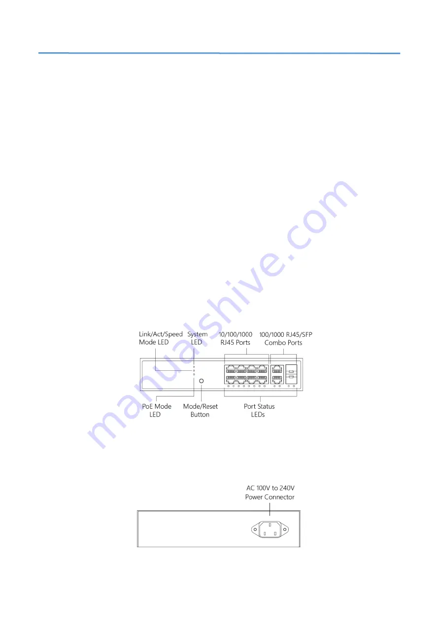
Front View of the Switch
Figure 1:Front panel of the switch
Rear View of the Switch
Figure2:Rear panel of the switch


