background image

5: Function Reference

F69 – Time Mode

Use function F69 to select the time type displayed by:

See "F1 – Time Zone Offset" on page 48

Select between the following types of time:

UTC (Coordinated Universal Time)

differs from GPS Time by the addition of leap-

second corrections to compensate for variations in the earth’s rotation.

GPS Time

is derived directly from the GPS constellation and doesn’t contain any leap-

second adjustments or other GPS-to-UTC corrections.

Standard Time

is UTC plus a time zone adjustment. For example, Pacific Standard

Time is UTC minus 8 hours

Local Time

is UTC plus a time zone and a daylight saving time adjustment.

The factory setting is UTC. Local Time modifies UTC time to include the Time Zone and
Daylight Saving Time adjustments, if enabled by the user.

Related functions:

“F90 – Code Output Configuration” on page 105

“F1 – Time Zone Offset” on page 48

Command Line

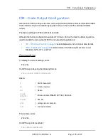
Use the following format to display the time mode currently used:

F69<CR>

F69 responds using the following format:

F69<S><TT><CR><LF>

where:

F69

= Function number 69

<S>

= ASCII space character.

<TT>

= Time Type. Either GPS, UTC, LOCAL, or STANDARD.

<CR>

= Carriage return character.

<LF>

= Line feed character.

Page 90 of 221

.................................

098-00116-000 Rev. A

Summary of Contents for XL-GPS

Page 1: ...XL GPS Time Frequency Receiver User Guide CD Part Number 098 00116 000 Rev A 5 May 2010 ...

Page 2: ...com Copyright 2010 Symmetricom Inc All rights reserved Printed in U S A All product names service marks trademarks and registered trademarks used in this document are the property of their respective owners The contents in this manual do not apply to previously released versions of XL GPS hard ware or software ii ...

Page 3: ...se or of any other kind or description whatsoever By purchasing any product manufactured by Symmetricom the buyer consents to and agrees with Symmetricom that as a result of the exclusion of all warranties expressed or implied of merchantability fitness for purpose or otherwise except for the limited one year warranty for defects in material and workmanship for products manufactured by Symmetricom...

Page 4: ...mbodies proprietary and confidential information and is the exclusive property of Symmetricom Inc It may not be reproduced used or disclosed to others for any purpose except that for which it is purchased or loaned About this Manual This manual is subject to change without notice Symmetricom can not be held responsible for any errors or inaccuracies in this manual Please notify the Customer Assist...

Page 5: ...verview of the XL GPS Time and Frequency Receiver 1 Product Description and Features 1 2 System Specifications 3 Chassis 3 Environmental 4 Time and Frequency Accuracy 4 GPS Reference 4 AC Power Supply 5 Input 5 Standard I O 5 RS 232 RS 422 Interface 5 Network Port 10 100 6 J1 Optional TI ET 6 J2 Rate Out 7 J2 Optional Programmable Pulse Out PPO 7 J3 Optional Frequency Measurement 7 1 PPS Out 8 v ...

Page 6: ... 04 W IEEE1344 12 Output 13 Time Code Inputs 13 Time Code Outputs 13 Time Code Input IRIG B120 200 04 W IEEE1344 14 XL GPS SYNC 14 Input 15 Time Code Input IRIG B000 200 04 W IEEE1344 15 XL GPS SYNC 15 GPS Time and Frequency Reference 16 Summary of Options 16 Expansion Module 87 8134 1 16 Multi code Outputs 87 6002 XL1 16 1 5 10 MHZ SINE AND MPPS 87 8108 17 10MHZ Sine Output Low Phase Noise 17 Net...

Page 7: ... Signal Strength Requirements 23 WARNING GPS Position and Altitude 25 Mounting Safety Considerations 25 Making Additional Connections 27 Make the following optional connections 28 Connecting the Power Supply 28 CAUTION VAC power 28 WARNING Removing Power 29 CAUTION Stopping the XL GPS 29 Configuring the Network Port 29 Configuring the Time Display 30 Using the Command Line Interface 31 Connecting ...

Page 8: ...37 Status Display 38 Menu Display 39 Keypad Operation 39 Keypad Examples 40 Command Line Interface 41 Logging In 42 Operator Login 42 Guest Login 42 Logging Out 42 Changing Username and Password 42 Session Timeout and Priority 43 5 Function Reference 45 Function Summary 45 F1 Time Zone Offset 48 F2 12 24 Hour Format 50 F3 Time Date 52 F4 Serial Port Configuration 54 F5 Time Quality Setup 56 viii ...

Page 9: ...ation Mode 79 F60 GPS Receiver Satellite List 81 F66 Daylight Saving Time DST Mode 84 F67 Manual Leap Seconds Entry Request 87 F69 Time Mode 90 F71 Oscillator Statistics 92 F72 Fault Status 94 F73 Alarm Control Status 95 F90 Code Output Configuration 105 F100 Network Port Configuration XL GPS Firmware 107 F100 EA Ethernet Address 109 F100 IP IP Address 109 F100 SM Subnet Mask 111 F100 G Gateway 11...

Page 10: ...eboot 122 F100 P Change User Password 123 F100 PI PING 124 F100 PN Change User Name 125 F108 Oscillator Configuration 127 F110 J1 Input Time Code TIET 128 F111 J2 Output Rate PPO 133 F113 J3 Input Freq Meas 138 F117 Factory Configuration 142 F119 GPS Receiver Configuration 143 F126 Options Key Entry 149 Default Values for Standard Functions 150 6 Option Cards 151 Expansion Module 87 8134 1 87 8134...

Page 11: ...sting Amplitude and Modulation Ratio 159 10 MHz Sine Output LPN Option Card 87 8114 160 1 5 10 MHz Sine MPPS Square Output 87 8108 161 Introduction 161 Specifications 161 1 MHz Output 161 5 MHz Output 161 10 MHz Output 162 1 MPPS Output 162 5 MPPS Output 162 10 MPPS Output 163 Installation 163 Sine Wave Outputs 163 Square Wave Outputs 163 Maintenance 163 Equipment Required 164 No Output Or Outputs...

Page 12: ... the FTP Server Workstation 171 Copy the Configuration Files to the FTP Server 172 Edit the Configuration Files 173 Move the Configuration Files Back to the XL GPS 173 B Upgrading System Firmware 175 Overview of Procedure 175 Set up the FTP Server 175 Open a Command Line Session on the XL GPS 176 Upgrade the Firmware 176 Troubleshooting 179 FAQ 180 C SNMP 183 SNMP Private Enterprise MIB Structure ...

Page 13: ... Procedure 193 D Network Time Protocol NTP 195 Editing ntp conf 195 Editing MD5 keys on the XL GPS 196 Editing MD5 keys on the NTP Client 196 E Time Code Formats 198 Overview 198 IRIG 198 Introduction 198 IRIG Code Format 198 IRIG B Time Quality Flags 199 Output 199 F World Map of Time Zones 202 G Part Names 203 H Sales and Customer Assistance 204 I Certificate of Volatility 206 J Declaration of C...

Page 14: ......

Page 15: ...front panel of the XL GPS The standard configuration includes 1U chassis GPS receiver Liquid crystal display LCD and a 19 button keypad 10 MHz and 1 Pulse sec discrete output signals via rear panel BNC connectors RS 232 or RS 422 via rear panel 9 pin D Male Network Port 10 100 Base T for TELNET and SNMP Rate Out 1 10 100 PPS 1 10 100 kPPS 1 5 10 MPPS 1 output via a rear panel BNC Code Output IRIG ...

Page 16: ...led using a software key at any time Network Time Server NTS Programmable Pulse Output PPO Time Interval Event Time TI ET Frequency Measurement FREQ MEAS The optional OCXO oscillator upgrade provides enhanced short term stability while locked to GPS and improved holdover flywheeling when GPS is unavailable Page 2 of 221 098 00116 000 Rev A ...

Page 17: ...cations Chassis The chassis is a 19 inch rack mounted 1U chassis Size 1 75 in x 17 1 in x 14 in Weight 8 lbs Standard Hardware Standard 19 EIA rack system Optional Hardware Slide rack hardware 098 00116 000 Rev A Page 3 of 221 ...

Page 18: ...5 CFM AVERTISSEMENT Installez le XL GPS pour permettre un flux d air autour et a travers l unité Symmetricom recommande de laisser 1 4 in 3 6 cm au dessus et au dessous du XL GPS ou assez d espace pour permettre 5 CFM Time and Frequency Accuracy GPS Reference Time and frequency accuracy stability while locked to a GPS timing reference 1 PPS Output 30 nS RMS UTC USNO Frequency Output Accuracy 1 x 1...

Page 19: ...imum Standard I O The following specifications apply to the connectors on the Main CPU card RS 232 RS 422 Interface The standard serial data port is a bi directional EIA standard RS 232C interface The serial data port is configurable via the Keypad and Network Port Interface RS 232 RS 422 Data Rates 1200 2400 4800 9600 and 19200 bps Data Bits 7 or 8 Parity even odd or none for Data Bits 8 even or ...

Page 20: ...an external 1 PPS or Event input signal and measures it against the system derived time The minimum pulse width of the input signal is 100 nS The input impedance is selectable at 100 kW or 50 W The rising edge of the pulse is measured with 5 nS resolution relative to the system clock time Pulse width 100 nS min Active Edge Rising High Level Logic Hi 1 25 V 10 V Low Level Logic Low 1 25 V 0 V Imped...

Page 21: ...pulse width in integer multiples of 1 mS The rising edge of the trigger output can be programmed to occur with 1 mS resolution Pulse width Programmable in 1 mS steps On time edge Rising Amplitude 2V 10 into 50 W J3 Optional Frequency Measurement The Frequency Measurement Freq Meas option measures an external frequency applied to the J3 input relative to the XL GPS disciplined frequency Frequency 1...

Page 22: ... 10 Amplitude DC TTL into 50 W Qty 1 Connector BNC female Phasing In phase with carrier 10 mS Accuracy Refer to Time and Frequency Accuracy on page 4 Five flags are encoded in the control function segment of the IRIG B code IRIG B 120 B000 B120 1344 B000 1344 The first flag encoded at element P5 40ms is the LOCK indicator It is a binary 1 when the reference source has become unlocked The second fl...

Page 23: ...de of operation allows proper maintenance of UTC by the XL GPS when utilizing a time reference source that does not contain leap second data Manual leap second entry could also be beneficial when operating in a free run mode i e no external reference or in an extended holdover mode Locked reference sources containing leap second data GPS and IRIG B w IEEE1344 shall take priority to the manual leap...

Page 24: ...ap second Where necessary use the Up Down keys to add or subtract a leap secondnone add or sub in March June September or December and year 6 Enter Discrete 10 MHz Output Signal Type Analog sine wave Synchronization Phase coherent to the clock 10MHz and 1PPS to within 10ns Amplitude 13 dBm 1 5 dBm into 50 Ω Qty One Connector BNC female Frequency stability while locked to GPS Overlapping Allan Devi...

Page 25: ...tal and relativistic effects It is the primary realisation of Terrestrial Time Discrete 1PPS Output Signal Type 2V into 50 Ω with a fixed 12ns 8ns delay with respect to the CPU 1PPS Output Time Code Output IRIG B120 200 04 W IEEE1344 The selectable Code output will have an additional selection for IRIG B 120 w IEEE1344 configuration is via the Keypad Display RS232 422 and the Network port via teln...

Page 26: ...1PPS 10 mS Time Code Output IRIG B000 200 04 W IEEE1344 The selectable Code output provides a selection for IRIG B 000 w IEEE1344 IRIG A000 and NASA 36 are also available as outputs Configuration is made via the l Keypad Display l RS232 422 9600 l Network port via telnet IRIG B 000 IS DEFINED IN IRIG STANDARD 200 04 AS Format B 100 pps 0 Pulse width code 0 No carrier index count interval 0 BCDTOY ...

Page 27: ...Vp p to 10 Vp p 10 100 kΩ to ground Ratio AM 3 1 10 Amplitude DC l Logic Low 1 5V l Logic Hi 2 5V Bandwidth 50 Hz to 250 kHz Impedance 100 kΩ or 50 Ω with DC code 100 kΩ with AM code Polarity positive or negative Direction Forward Qty 1 Connector BNC female Time Code Outputs The Code output default is IRIG B 120 AM IRIG configuration is via the Keypad Dis play RS232 422 and the Network port telnet...

Page 28: ...ase time error exceeds threshold 2 Element P5 80ms encodes a binary 1 when the error exceeds threshold 3 and P5 90ms when the error exceeds threshold 4 Time Code Input IRIG B120 200 04 W IEEE1344 The selectable Code input will have an additional selection for IRIG B 120 w IEEE 1344 configuration is via the Keypad Display RS232 422 and the Network port via telnet IRIG B 120 as Defined in IRIG STAND...

Page 29: ...via telnet IRIG B 007 as defined in IRIG STANDARD 200 04 as Format B 100 pps 0 Pulse width code 0 No carrier index count interval 0 BCDTOY CF SBS IEEE1344 as defined in IEEE1344 1995 R2001 ANNEX F see section 3 3 definitions XL GPS SYNC The XL GPS shall first synchronize to IRIG B 000 w IEEE1344 when the Time Quality control bits are 0000 The XL GPS shall remain synchronized Locked while the Time ...

Page 30: ...s are available with the XL GPS For more information go to the cross references associated with each one Expansion Module 87 8134 1 The expansion module provides four independently configurable outputs The outputs are configured using jumper switch settings on the Expansion Module These are configured at the factory per the sales order and can also be configured by the user in the field For more i...

Page 31: ...ly available with the optional OCXO and is internally cabled to the oscillator installed in the XL GPS For more information See 10 MHz Sine Output LPN Option Card 87 8114 on page 160 OCXO Oscillator Option 87 399 30 For more informationSee Oscillators on page 18 Network Time Protocol Option The XL GPS can function as a Network Time Protocol NTP server when the Network Time Server NTS option is ins...

Page 32: ...1 x 10 9 1 sec 3 x 10 10 10 sec 3 x 10 10 100 sec 2 x 10 10 1000 sec 1 x 10 12 1 day Temperature 5x10 7 over 0 C to 50 C when not locked to GPS OCXO Oscillator option 87 399 30 Accuracy Function of input synchronization source Frequency Timing Stability Allan Deviation 1 x 10 10 1 sec 1 x 10 10 1000 sec 1 x 10 12 1 day Temperature 1 x 10 8 over 0 C to 50 C when not locked to a reference Aging 5 x ...

Page 33: ... Electromagnetic Compatibility EMC Directive Calibration Statement This unit does not contain user serviceable parts and does not require calibration Volatility Statement See I Certificate of Volatility on page 206 for the XL GPS Default parameters are stored one at a time through the function commands within the XL GPS CPU module 089 00205 000 There is no global clear command to restore default c...

Page 34: ......

Page 35: ...e For test situations a GPS antenna can be placed in a window Equatorial facing e g south facing for users in the northern hemisphere windows provide the best visibility of satellites However if the equatorial facing window has large obstructions such as trees or buildings a window facing another direction with fewer obstructions may be better Metal window shades and special metallic window coatin...

Page 36: ...t use a BNC T connector The L1 GPS antenna is designed to operate with up to 150 ft 60 96 m of RG 59 coax cable An optional Down Converter can be used for cable runs of 1 500 ft 457 2 m using RG 58 coaxial cable Antenna Construction The antenna is housed in completely waterproof packaging designed to with stand the elements When the four UNC4 40 screws in Figure A are loosened the antenna module d...

Page 37: ...oot length of RG 59 coax cable of has a loss of 16 21 dB which meets this requirement Abide by the minimum input gain requirements if using other cable types Additionally if changing the antenna abide by the 41 dB gain requirement Other factors such as radiation coverage VSWR and input impedance also affect system performance Symmetricom recommends using the standard antenna and cable provided wit...

Page 38: ...3 Installation Configuration Figure 2 GPS Signal Strength Requirements Page 24 of 221 098 00116 000 Rev A ...

Page 39: ...ation l Observe local codes and regulations l Use a lightning arrestor when needed l Antennas not rated for 12 VDC may be damaged when connected to the XL GPS The GPS antenna supplied with the XL GPS is rated for 12 VDC Safe Antenna and Cable Connection An outside antenna or cable system must be properly grounded to provide some protection against built up static charges and voltage Section 810 of...

Page 40: ...sources as this could be fatal AVERTISSEMENT l Evitez et les dangers de sûreté électriques et RF tels que les lignes à haute tension et les antennes de transmission de radio de haute énergie l Où les dangers potentiels existent ayez un technicien qualifié exécute l installation l Observez des codes et des règlements locaux l Utilisez un arrestor d éclair quand nécessaire l Les antennes qui n ont p...

Page 41: ... placement de l unité de décharge d antenne le reliment aux électrodes de la mise à la terre et les conditions requises pour l électrode de la mise à la terre Gardez l Espace Libre d Antenne des Lignes Electriques ou des Circuits à Haute Tension Localisez un puits extérieur de système d antenne loin des lignes électriques et des circuits de lumière électrique ou de puissance a fin qu il ne touche ...

Page 42: ... Power Supply Connect the Power Supply to a power source Upon receiving power the XL GPS goes through its startup sequence displaying Booting Loading and then Starting After approximately 40 seconds the XL GPS displays the clock status and user interfaces front panel command line become available See Grounding on page 34 CAUTION VAC power l The VAC Power Supply specification reflects the overall P...

Page 43: ... avant d enlever le courant Configuring the Network Port The following additional steps are required to make the XL GPS operational on a network Make the XL GPS operational on a network if you plan on Managing the XL GPS remotely over the network Distributing timing information from the XL GPS over the network Press Result ENTER Displays FUNCTION 100 Enters 100 as the function number ENTER Display...

Page 44: ...mat F2 12 24 Hour Format on page 50 Select a 12 or 24 hour display format By default the XL GPS is set to the 24 hour display format e g 6 P M is displayed as 18 00 F66 Daylight Saving Time DST F66 Daylight Saving Time DST Mode on page 84 If needed set when Local time enters and leaves DST The factory settings for F66 apply to most users in the continental US DST begins at 2 A M on the 2nd Sunday ...

Page 45: ...essibility over a network through the standard network port To use the command line interface refer to the explanations and examples in the Command Line subsections for each function Connecting to the Serial Port Complete the following steps to set up and use the Serial Port to communicate with the XL GPS Verify that the XL GPS s serial port settings are as follows Keypad ENTER 4 ENTER Use the UP ...

Page 46: ...07 or F100 IP IP Address page 109 to obtain the XL GPS s IP address 2 Open a telnet session from your PC to the XL GPS In Windows click Start Run enter telnet where the s are the XL GPS s IP address and click OK Open a telnet session using a program such as HyperTerminal TeraTerm Pro or Minicom Consult the program s documentation for instructions 3 Log in as user name operator and password janus P...

Page 47: ...ed to mount the XL GPS securely in any EIA standard 19 inch 48 26 cm rack 2 mounting brackets 4 flat head Phillips screws Have the following items ready and available The appropriate AC or DC power source to connect to the XL GPS s power supply A 2 size Phillips bit screwdriver To rack mount the XL GPS Unscrew the four phillips head screws from the front end of the side panels Use the same screws ...

Page 48: ...t the chassis grounding screw to a reliable earth ground AVERTISSEMENT Symmetricom recommande que le châssis soit relié à une terre fia ble Proper Grounding Maintain reliable grounding earthing of rack mounted equipment The ground screw provided with the XL GPS instrument is a stainless steel pan head 10 32 0 375 inch long machine screw Grounding the XL GPS l For VAC power verify that a properly g...

Page 49: ...ich is 0 C to 50 C or 32 F to 122 F Reduced Air Flow Position the XL GPS with enough space above below and adjacent to the chassis to allow an adequate flow of air so that it may operate safely Symmetricom rec ommends leaving 1 4 in 3 6 cm above and below the XL GPS or enough space to allow 5 CFM air flow Uneven Mechanical Loading Mount the equipment so as to avoid uneven mechanical load ing that ...

Page 50: ......

Page 51: ...n but hasn t elapsed Red An alarm has been triggered Check F73 to find out what the fault unlock condition is and take appropriate action Notes The amber LED can turn green again while the reference source input remains unlocked This is because F119 s GPS Status controls whether the LED turns amber F73 s Timeout Delay controls how long the LED remains amber The blinking of the LED has no meaning I...

Page 52: ...us Display comes up automatically when the XL GPS is rebooted To manually switch from another display to the Status Display press STATUS button on the keypad The keypad appears as follows STATUS REF CLK TYPE DDD HH MM SS YYYY For example LOCKED GPS UTC 200 21 24 09 2009 where LOCKED System Clock Status is Locked or Unlocked to the current reference source See Clock Status in F73 Alarm Control Stat...

Page 53: ...FFSET F1 TIME ZONE OFFSET Pressing the UP ARROW key increments to the next function F2 12 24 HOUR FORMAT and so on Pressing the DOWN ARROW key skips to the highest available function F126 OPTIONS KEY ENTRY and from there decrements through the functions The section 5 Function Reference on page 45 provides detailed information on all of the XL GPS s functions Keypad Operation Use XL GPS s front pan...

Page 54: ... examples show how to use the keypad effectively To open a function using ENTER Press Result ENTER Displays the FUNCTION prompt 2 Enter the function s number 2 in this example ENTER Displays F2 s first screen DISPLAY HOUR FORMAT 24 HOUR To open a function using MENU Press Result MENU Displays F1 on the front panel display UP DOWN ARROW Scrolls through the list of functions ENTER Opens the function...

Page 55: ...nd displays the Status Display To enter numeric values in a function Press Result ENTER Displays the FUNCTION prompt 3 Enters 3 as the function number ENTER Opens Function 3 displays the first screen TIME MODE LOCAL ENTER Displays the second parameter DATE TIME mm dd yyyy 01232010 Enters January 23 2010 as today s date replace ENTER Displays DATE TIME ENTER XL GPS asks SAVE CHANGES YES ENTER Selec...

Page 56: ...erator the only command line interface function you cannot perform is changing the Guest password Guest Login Use the guest login to view function settings As shipped you can log in as guest using User Name guest Password ttm To maintain security change the Guest password at installation If you try to use a function that is not accessible from the guest login you will see a message such as Access ...

Page 57: ...control to the network port again The network port will show a prompt but will not accept additional commands after the serial port has taken control back At this point closing the network port connection and opening a new one will also fail a network port connection cannot be re established until the serial port has been closed The following transcripts show the results of a contest between a ser...

Page 58: ...er Interfaces NOTICE UTILITY MONITOR SESSION HAS TAKEN PRIORITY FROM THIS TELNET SESSION f100 ic NOTICE CANNOT RESPOND TO COMMAND BECAUSE UTILITY PORT SESSION HAS PRIORITY Page 44 of 221 098 00116 000 Rev A ...

Page 59: ... F6 Keypad Lock K N S Lock keypad access to the XL GPS s functions When locked F6 is the only function available from the keypad F8 Continuous Time Once per Second N S Output the time once per second to the command line F9 Time On Request N S Output the time when triggered to the command line F11 Time Output For mat N S Change the format of the time output by F8 and F9 F13 Time Error K N S View th...

Page 60: ...le or disable LED blink F90 Code Output Configuration K N S Configure settings for CODE time code output F100 Network Port Configuration XL GPS Firmware K N S Configure the standard network port settings F100 EA Ethernet Address K N S Display the Ethernet MAC address F100 IP IP Address K N S Configure the IP address F100 SM Subnet Mask K N S Configure the subnet mask F100 G Gateway K N S Configure...

Page 61: ...tus of the factory mode jumper which is used by factory technicians Not of interest to most end users F100 K I L L Reboot N S Reboot the XL GPS F100 P Change User Password N S Change the XL GPS password F100 PI PING N S Ping from the XL GPS to another host on the network F100 PN Change User Name N S Change the User Name F108 Oscillator Configuration K N S View the oscillator type F110 J1 Input Tim...

Page 62: ...light Saving Time DST Mode on page 84 Because the front panel display can be configured to display distribute Local or Standard time we recommend configuring F1 as described in the 3 Installation Configuration on page 21 The factory setting for F1 is UTC 8 00 hours Pacific Standard Time Related topics l F2 12 24 Hour Format on page 50 l F11 Time Output Format on page 64 See F11 Time Output Format ...

Page 63: ...s offset CR carriage return character LF line feed character For example to set the time zone offset enter F1 8 00 CR XL GPS responds OK CR LF To verify the change enter F1 CR XL GPS Responds F1 8 00 CR LF 098 00116 000 Rev A Page 49 of 221 ...

Page 64: ...00 00 Another example in the 24 hour format 18 00 is equivalent to 6 00 PM in the 12 hour format i e 18 00 12 00 6 00 PM Note Local time is commonly displayed in both 12 and 24 formats The specifications for Standard UTC and GPS call for using the 24 hour format Applying the 12 hour for mat to any time type leads to ambiguous time notation For example if the 12 hour format is applied to UTC the cl...

Page 65: ...SCII character for IRIG format CR Carriage return character LF Line feed character For example to display the current hour format send F2 CR XL GPS responds F2 D24 I24 CR LF To set the hour format send F2 D12 I24 CR XL GPS responds OK CR LF 098 00116 000 Rev A Page 51 of 221 ...

Page 66: ...00 F3 defines only the entry of tim in F3 it does not control the type of time displayed or output by the XL GPS F3 s Time Mode should not be confused with F69 see F69 Time Mode on page 90 F69 controls the type of time displayed output on the front panel display F8 Continuous Time Once per Second on page 60 and F90 Code Output Configuration See Factory Default Jumper and Switch Settings for Option...

Page 67: ...r digit year ASCII character for slash delimiter ASCII character for a colon delimiter hh one or two digit hours mm two digit minutes ss two digit seconds CR carriage return character LF line feed character For example to display the date and time send F3 CR XL GPS responds F3 UTC 01 01 2009 00 05 34 CR LF To set the time and date send F3 UTC 07 14 2009 18 20 30 CR Note Only valid times and dates ...

Page 68: ...sponds F4 S RS SEP BR SEP DB SEP P SEP SB CR LF where F ASCII character F 04 function number S ASCII space character one or more SEP One or more separator characters either space comma or tab The separator character is used to separate the following parameters RS BR DB P and SB RS Interface type RS 232 or RS 422 BR Baud Rate with possible values 1200 2400 4800 9600 or 19200 DB Data Bits with possi...

Page 69: ...able valid when Data Bits is set to 8 For example to display the serial port settings send F4 CR XL GPS responds F4 232 9600 8 none 1 CR LF To set the serial port settings send F4 422 9600 7 even 1 CR XL GPS responds OK CR LF 098 00116 000 Rev A Page 55 of 221 ...

Page 70: ...8 Continuous Time Once per Second on page 60 In addition a time quality indicator is encoded in the time codes that carry time quality information i e IRIG IEEE 1344 see F90 Code Output Configuration on page 105 The XL GPS accepts threshold values from 200 nS to 40000000000 nS The factory settings for F5 are as follows Time quality reporting enabled First time quality flag 1 000 ns Second time qua...

Page 71: ... quality status and flags enter F5 CR If F5 is enabled XL GPS responds example F5 ENABLE 00000001000 00000010000 00000100000 00001000000 CR LF If F5 is disabled XL GPS responds F5 DISABLE CR LF To enable time quality reporting and change the thresholds of the time quality flags enter F5 ENABLE 2000 20000 200000 2000000 CR XL GPS responds OK CR LF Note Leading zeros aren t required when entering ne...

Page 72: ...Lock is disabled See Factory Default Jumper and Switch Settings for Options on page 166 Command Line To display the Keypad Lock status send F6 CR XL GPS responds F6 S STATE CR LF where F ASCII character F 6 function number S ASCII space character one or more STATE ENABLE or DISABLE CR carriage return character LF line feed character For example to display the Keypad Lock status send F6 CR XL GPS r...

Page 73: ...F6 Keypad Lock To disable Keypad Lock send the following string F6 DISABLE CR XL GPS responds OK CR LF 098 00116 000 Rev A Page 59 of 221 ...

Page 74: ... 16 00 14 365 16 00 15 365 16 00 16 365 16 00 17 199 13 56 03 199 13 56 04 In the first two lines above the unsynchronized time is followed by a time quality character In this case the indicates that the XL GPS is unlocked to a reference source As the XL GPS locks to the reference source the disappears and after a couple seconds the new synchronized time of year information appears If the referenc...

Page 75: ...lity flag 2 s threshold Time error has exceeded time quality flag 3 s threshold Time error has exceeded time quality flag 4 s threshold Or A reference source is unavailable The four time quality thresholds are set by F5 Time Quality Setup See F13 Time Error on page 67 for more information Command Line For example to initiate Continuous Time once per second enter F8 CR The XL GPS replies 199 11 19 ...

Page 76: ...each time it receives a T until F9 is cancelled To cancel this function enter Ctrl C on your keyboard The command line disregards any input other than SHIFT T until it receives a Ctrl C command The time of day output is only available on the port network or serial that was used to give the F9 command The default output string is as follows SOH DDD HH MM SS mmmQ CR LF where SOH ASCII Start of Headi...

Page 77: ...s threshold Time error has exceeded time quality flag 4 s threshold or a reference source is unavailable For example to prepare Time on Request enter F9 CR Then to request the current time enter SHIFT T on your keyboard T does not appear on the command line XL GPS responds SOH 128 20 30 04 357 CR LF To exit F9 press Ctrl C on your keyboard 098 00116 000 Rev A Page 63 of 221 ...

Page 78: ...F ASCII Line Feed character DDD Day of year HH Hours MM Minutes SS Seconds ASCII decimal point mmm Milliseconds Colon separator Q Time quality character table below The time quality character Q is one of the following characters SPACE Time error is less than time quality flag 1 s threshold Time error has exceeded time quality flag 1 s threshold Time error has exceeded time quality flag 2 s thresho...

Page 79: ...ove with an X F11 SEP DDD HH MM SS mmmQ CR F11 does not control the SOH CR or LF in the F8 output strings SEP is only one character wide either a space comma or tab Any character other than an upper case X in a numeric position does not affect the output of that position The colons or decimal point however may be replaced with any single ASCII character except null Hex 00 carriage return or line f...

Page 80: ...e return the remaining un typed characters are enabled and assume their default values For example if you enter F11 TAB XXX CR XL GPS responds OK CR With the above settings F8 displays SOH 10 45 01 CR LF With the above settings F9 displays SOH 10 45 01 234 CR LF The new time format above suppresses days and replaces the first colon separator with a vertical bar This enables the remaining character...

Page 81: ... calculates the worst case time error based on the stability of system clock s oscillator type and the time elapsed since loss of lock Command Line The Command line interface will report time error when it receives the following string F13 CR XL GPS responds F13 S ERROR CR LF where F13 ASCII string for function F13 S ASCII space character ERROR calculated worst case error in seconds CR carriage re...

Page 82: ...oftware firmware File System Project Rev FPGA Command Line Use Command Line Function F18 to obtain the system s firmware version information For example enter F18 CR XL GPS responds F18 BOOTLOADER 084 00251 000V1 82 1 15 SOFTWARE 084 00217 000V1 82 1 15 FILE SYSTEM 084 00359 000V1 82 1 15 PROJ REV 2 1 FPGA 084 00360 000V65 Page 68 of 221 098 00116 000 Rev A ...

Page 83: ...t will respond as follows F42 B 1 The Multicode output card channel code setting may be requested using the following com mand F42 SP O SP C CR where SP one space O ASCII character indicating output port C channel number 1 to 4 The serial port will respond with the channel code for the selected channel The following example requests the code from channel 1 F42 O 1 CR LF The serial port will respon...

Page 84: ...ge Return for input strings and the serial port will respond with the following ASCII string OK CR LF The following example sets port 2 to IRIG B 123 F42 O 1 IRIG B 123 and the serial port will respond with the following ASCII string OK CR LF The following example sets port 1 plus all ports that have been assigned to IRIG A the out put time code of IRIG A 133 F42 O 1 IRIG A 133 and the serial port...

Page 85: ...ting that time reference will be set SP one space TREF Time Reference UTC LOCAL STANDARD or GPS and the serial port will respond with the following ASCII string OK CR LF The Serial Network port will respond with the message ERROR 01 VALUE OUT OF RANGE if the input string was in the correct format but contained a value probably numeric that was out of the range of acceptable values The Serial Netwo...

Page 86: ...s intersects the sphere of the earth at the 0 latitude 0 longitude If LLA is selected Altitude Mode shows the elevation in meters WGS 84 Warning This GPS receiver is optimized for timing versus position accuracy Therefore position information on this unit is not recommended for navigation and other critical position applications Keypad When Position Mode is LLA the position of the antenna is displ...

Page 87: ...at F50 S SIGN S DEG d MIN SEC S SIGN S DEG d MIN SEC S ALT UNITS CR LF where F50 Function 50 S ASCII space character one or more SEP Separator LLA LLA mode CR carriage return character SIGN N or S for latitude E or W for longitude for negative altitude and S or for positive altitude DEG two digit degrees for latitude or three digit degrees for longitude d ASCII character d MIN two digit minutes AS...

Page 88: ... S MY m S SIGN MZ m CR LF where F ASCII character F 50 function number S ASCII space character SIGN Either or for the position of the ECEF XYZ coordinates MX Antenna X position in meters to tenths of a meter MY Antenna Y position in meters to tenths of a meter MZ Antenna Z position in meters to tenths of a meter m ASCII character m for Meters ALT altitude in meters CR carriage return character LF ...

Page 89: ... by 1 4 ns ft to get the value for F51 Don t use function F51 to adjust the XL GPS s timing outputs use F52 Distribution Cable Delay instead See Factory Default Jumper and Switch Settings for Options on page 166 Command Line Use the following format to display the current Antenna Cable Delay setting F51 CR The XL GPS responds using the following format F51 S DELAY ns CR LF where F ASCII character ...

Page 90: ...S responds F51 000060ns CR LF To set the antenna cable delay use the following format F51 S DELAY NS CR For example to set the antenna cable delay to 100 nS enter F51 100NS CR XL GPS responds OK CR LF Page 76 of 221 098 00116 000 Rev A ...

Page 91: ...lay foot by the length of the cable in feet The typical delays for the following cable types are RG 58 approximately 1 4 ns foot RG 59 approximately 1 24 ns foot See Factory Default Jumper and Switch Settings for Options on page 166 Command Line To display the current distribution cable delay enter F52 CR The XL GPS responds using the following format F52 SEP SIGN DELAY ns CR LF where F ASCII char...

Page 92: ...5 Function Reference XL GPS responds F52 000000ns CR LF To set the distribution cable delay to 60 nS enter F52 000060nS CR XL GPS responds OK CR LF Page 78 of 221 098 00116 000 Rev A ...

Page 93: ...position data over time to determine the antenna position and calculate the time precisely and accurately See Factory Default Jumper and Switch Settings for Options on page 166 Keypad While viewing the Status screen on the XL GPS front panel display press the following keypad buttons ENTER 53 ENTER If a GPS Receiver is not available F53 displays GPS AVAILABILITY NOT AVAILABLE Note If F53 indicates...

Page 94: ...ce characters STATUS DYNAMIC MODE or TIME MODE CR carriage return character LF line feed character For example enter F53 CR Example response F53 TIME MODE or DYNAMIC MODE CR LF To set the GPS Operation Mode enter a command using the following format F53 SP MODE CR where MODE equals DYNAMIC MODE or TIME MODE For example enter F53 TIME MODE CR Or F53 DYNAMIC MODE CR F53 responds OK CR LF Page 80 of ...

Page 95: ...M feature has detected anomalous signals from this satellite and has quarantined it from the timing solution for 12 hours GPS satellite signal strengths are reported in units of dBW Signals below 170 dBW e g 171 dBW are not usable by the GPS receiver See GPS Signal Strength Requirements on page 23 If you re using the keypad interface use the UP DOWN ARROWs to scroll through the list of satellites ...

Page 96: ...t 162dBW F60 prn3 good current 163dBW F60 prn4 unknown F60 prn5 unknown F60 prn6 unknown F60 prn7 unknown F60 prn8 good current 161dBW F60 prn9 unknown F60 prn10 unknown F60 prn11 unknown F60 prn12 unknown F60 prn13 good current 159dBW F60 prn14 unknown F60 prn15 unknown F60 prn16 unknown F60 prn17 unknown F60 prn18 unknown F60 prn19 unknown F60 prn20 unknown F60 prn21 unknown F60 prn22 bad tracke...

Page 97: ...F60 GPS Receiver Satellite List F60 prn32 unknown Similarly to display a list of the current tracked bad or rejected satellites enter F60 CURRENT CR Or F60 TRACKED CR 098 00116 000 Rev A Page 83 of 221 ...

Page 98: ...locations in the southern hemisphere where DST spans the new year See Factory Default Jumper and Switch Settings for Options on page 166 Command Line To display the current status of F66 enter a command using the following format F66 CR F66 responds using the following format F66 S STATE ENTER EXIT CR where F ASCII character F 66 function number S ASCII space character one or more STATE Off or Man...

Page 99: ... for last OUTDAY day in to exit DST 1 through 7 where Sunday is 1 OUTMONTH month to exit DST 1 through 12 where 1 is January CR carriage return character LF line feed character For example enter F66 MANUAL 02 1 1 04 02 0 1 10 Meaning Manual settings are in effect The entry time is 2 am on the 2nd Sunday of March The exit time is 2 am on the 1st Sunday of November To leave the value of any item unc...

Page 100: ...5 Function Reference If any of the items in an input string are invalid an error message will be returned Page 86 of 221 098 00116 000 Rev A ...

Page 101: ...h SELECT NONE ADD or SUB DATE Date of next leap second insertion or blank if SELECT is NONE CR carriage return character LF line feed character If the Manual Leap Second function is set with leap second event values the port will respond with the string described below Sample request F67 CR Response F67 14 33 ADD 12 31 2007 CR LF To set the current leap second value for UTC GPS enter a continuous ...

Page 102: ... month MAR JUN SEP DEC YEAR Year that the leap second will be subtracted 2000 to 2030 Subtracting a leap second To set the next leap second insertion time for subtracting a leap second enter a continuous string of the form F67 SP SUB SP MONTH SEP YEAR CR where SUB ASCII string indicating a leap second will be subtracted MONTH Month number that the leap second will be subtracted on the last day of ...

Page 103: ... was in the correct format but contained a value probably numeric that was out of the range of acceptable values The Serial Network port will respond with the message ERROR 02 SYNTAX if it receives a string in an incorrect format for example the second field should be S LS ADD SUB or NONE The Serial Network port will respond with the message ERROR 03 BAD MISSING FIELD if the input string lacks a r...

Page 104: ...justment For example Pacific Standard Time is UTC minus 8 hours Local Time is UTC plus a time zone and a daylight saving time adjustment The factory setting is UTC Local Time modifies UTC time to include the Time Zone and Daylight Saving Time adjustments if enabled by the user Related functions F90 Code Output Configuration on page 105 F1 Time Zone Offset on page 48 Command Line Use the following ...

Page 105: ...S TT CR where F ASCII character F 69 Function number S ASCII space character TT Time Type Either GPS UTC LOCAL or STANDARD CR carriage return character LF line feed character For example to change the time mode to local time enter F69 LOCAL CR Or to change the time mode to UTC enter F69 UTC CR F69 responds to these changes with OK CR LF RESETTING THE UNIT CR LF PLEASE WAIT CR LF 098 00116 000 Rev ...

Page 106: ...controls the DAC output voltage It ranges from 0 to 65536 Command Line To display the F71 settings enter F71 CR F71 responds using the following format F71 S phase SIGN MULT E SIGN EXP S s S S offset SIGN MULT E SIGN EXP S S drift SIGN MULT E SIGN EXP DAY S S DAC SIGN INT CR LF Note The display example above will be one unbroken line It is broken here into three lines for demonstration purposes wh...

Page 107: ...F71 Oscillator Statistics For example enter F71 CR F71 responds F71 PHASE 5 678E 09 s OFFSET 1 986E 07 DRIFT 6 013E 08 DAY DAC 24567 CR LF 098 00116 000 Rev A Page 93 of 221 ...

Page 108: ...Clock Phase Loop Lock status LOCKED or UNLOCKED CLOCK STATUS Clock Status LOCKED or UNLOCKED to the reference source shown The LOCKED state is based on the F73 Time Threshold value entered by the operator F73 Time Threshold sets the threshold in nS above which Time Error triggers an alarm When the oscillator s predicted worst case time error F13 Time Error on page 67 exceeds F73 Time Threshold Tim...

Page 109: ... depending on the options included at the XL GPS at the time it ships from the factory see items in the table that follows Update the alarm settings when adding or removing the expansion module from the XL GPS Indicator Parameter Name Status Factory Setting XL GPS without expansion module Clock Status Locked Unlocked Always Enabled PLL Locked Unlocked Alarm Enabled Low Phase Noise LPN PLL Locked L...

Page 110: ...MP on page 183 The following items may delay an unlocked or fault state from triggering an alarm immediately Timeout and Timeout Delay postpone Time Error alarms for a user configured interval See Timeout and Timeout Delay on page 98 Power on Alarm Suppress prevents alarms from being triggered for a user configured interval after the XL GPS boots and starts See Power On Alarm Suppress on page 98 A...

Page 111: ...alid GPS satellite signals and is generating a valid timing solution Unlocked The GPS receiver is not providing a valid timing solution due to one of the following causes Insufficient visibility of GPS satellites at the antenna location Poor GPS satellite signal strength A poorly positioned GPS antenna A broken or disconnected antenna cable An absent or non functioning GPS receiver card See Instal...

Page 112: ...lay can be used to prevent short term Time Error faults from triggering Time Error alarms Timeout Disabled All Time Error faults trigger an alarm regardless of duration Timeout Enabled Only Time Error faults that last longer than the Timeout Delay measured in seconds trigger an alarm If a Time Error fault clears and returns to an OK state before the Timeout Delay has elapsed the countdown stops an...

Page 113: ...e of a fault or unlocked state if the indicator is disabled The Alarm Latch is visible as an asterisk when viewing F73 on the front panel display For example GPS OK ALARM ENABLED Save Changes Yes Applies all user entered changes to the F73 configuration No Clears all user entered changes and exits the function Keypad Note The Alarm Latch asterisk is not the same as the reference source unavailable...

Page 114: ...7 not used 8 not used 9 Rb osc OK or not installed R Rb Osc Fault A DAC OK X DAC Fault B First time lock OK a Clock has locked since power on but still within the user defined power on time out A Clock has not locked since power on C Time error OK U Time error Fault D Timeout OK T Timeout Fault E NTP OK or option not enabled N NTP Fault F Future Use G Future Use H Future Use I Future Use J Future ...

Page 115: ...ollowing format F73 SP MASK SEP 123456789ABCDEFGHIJ CR LF Where the value of each character in 123456789ABCDEFGHIJ field is either E or D E means the corresponding indicator is enabled and can trigger an alarm if it enters a fault state D means the indicator is disabled or not available and will not trigger an alarm if it enters a fault state To enable E disable D or leave the indicator unchanged ...

Page 116: ...ed C E Time error Alarm Enabled D Time error Alarm Disabled D E Time out Alarm Enabled D Time out Alarm Disabled E D NTP Alarm Disabled Default if NTP Option not enabled E NTP Alarm Enabled Query or set Time Error Threshold using the THRESHOLD command To query the Time Error Threshold setting enter F73 SP THRESHOLD CR LF The XL GPS responds F73 SP THRESHOLD SP nanoseconds SP ns CR LF where nanosec...

Page 117: ...ommand string in the following format F73 SP TIMEOUT SEP seconds CR LF The XL GPS will set the new timeout delay and responds OK CR LF Led blinking can be ENABLED or DISABLED using the BLINK command To enable LED blinking enter F73 SP BLINK SEP ENABLE CR The XL GPS responds OK CR LF To disable LED blinking enter F73 SP BLINK SEP DISABLE CR The XL GPS responds OK CR LF Use the SUPPRESS command to s...

Page 118: ...nds from 0 to 86400 SP ASCII space character SEP one or more space characters either comma space or tab CR Carriage Return LF Line Feed To set the SUPPRESS enter a command using the following format F73 SP SUPPRESS SEP seconds CR The seconds can be set to any value from 0 to 86400 The XL GPS responds OK CR LF Page 104 of 221 098 00116 000 Rev A ...

Page 119: ...F90 for non standard applications F2 12 24 Hour Format on page 50 selects between a 12 or 24 hour time format F69 Time Mode on page 90 selects between the following timescales Local Standard GPS UTC and TAI Command Line To display the current settings enter F90 CR XL GPS responds using the following format F90 S CODE OUTPUT TYPE CR where F ASCII character F 90 function number S Space CODE OUTPUT I...

Page 120: ...ere F ASCII character F 90 function number SP space CODE OUTPUT IRIG B120 1344 or IRIG B000 1344 CR carriage return character LF line feed character Sample entry F90 SP IRIG B120 1344 CR Response OK CR LF The Serial Network port will respond with the message ERROR 01 VALUE OUT OF RANGE if the input string was in the correct format but contained a value probably numeric that was out of the range of...

Page 121: ...oth the keypad and the command line interface to access the following parameters Ethernet address XL GPS contains a unique Ethernet or Media Access Control MAC address comprised of a unique number assigned to the manufacturer and a unique number assigned to the unit This is factory set and cannot be changed IP Address Sets a static Internet Protocol IP address for the unit Subnet Mask Sets a valid...

Page 122: ...ut L for status LOCK UNLOCK Displays and configures Flash CRC ST Displays information RAM ST Displays information Serial ST Displays information Version Test NVRAM Ver ST Displays information Group 2 The following expanded command set is available through the command line interface Description F100 followed by Comments Burn Host BH Configure Burn BU Commit action Burn Bootloader BUB Commit action ...

Page 123: ...t The first three bytes are registered to Symmetricom Inc the last three bytes are the hex value identifying the network port To display the Ethernet address of the unit standard network port enter F100 EA CR XL GPS responds F100 EA 00 A0 69 xx xx xx CR LF where 00 A0 69 is the portion of the address assigned to the manufacturer and xx xx xx is unit s unique address in hexadecimal An example of th...

Page 124: ... and F100 G can be concatenated to set all three values simultaneously To do so use the following format F100 S IP S nnn nnn nnn nnn S SM S nnn nnn nnn nnn S G S nnn nnn nn n nnn CR Note The three commands i e IP SM G can be used in any order relative to each other A colon separator can be used instead of S following IP SM and G e g IP 192 168 46 150 For example using appropriate values for your n...

Page 125: ... nnn CR where F ASCII character F 100 unit function number S space IP specify IP command nnn nnn nnn nnn dotted decimal address 0 to 255 CR input line terminator For example enter F100 SM 255 255 255 240 CR XL GPS responds OK CR LF RESETING THE UNIT CR LF PLEASE WAIT CR LF To obtain the Subnet Mask of the unit Standard network port enter F100 SM CR XL GPS responds F100 SM nnn nnn nnn nnn CR LF whe...

Page 126: ...where F ASCII character F 100 unit function number S space IP specify IP command nnn nnn nnn nnn dotted decimal address 0 to 255 CR input line terminator For example enter F100 G 206 54 0 17 CR XL GPS responds OK CR LF RESETING THE UNIT CR LF PLEASE WAIT CR LF To obtain the Default Gateway of the unit Standard network port enter F100 G CR XL GPS responds F100 G nnn nnn nnn nnn CR LF where nnn nnn ...

Page 127: ...ion the user also has the option of selecting between 10 Base T and Auto If you have questions about your unit contact H Sales and Customer Assistance page 204 To display the current Base T setting enter F100 S BASET CR where F ASCII character F 100 unit function number S Space BASET specify Base T command CR input line terminator XL GPS responds F100 BASET 10T CR LF To set the Ethernet port to au...

Page 128: ...0 L and F100 LOCK terminates any active network sessions and prevents future network sessions To unlock F100 L or F100 LOCK use the serial port command line interface or the keypad display To lock the unit from a remote location enter F100 LOCK CR where F ASCII character F 100 unit function number S space LOCK specify LOCK command CR input line terminator For example enter F100 LOCK CR To users on...

Page 129: ...ter F 100 unit function number S space L specify L command CR input line terminator XL GPS responds F100 L LOCKED CR LF or F100 L UNLOCKED CR LF F100 ST Self Test Status Use function F100 ST to display whether the Self Test Status parameters passed or failed The parameters include flash memory checksum test nonvolatile NV RAM Serial Port and version check To query the self test status enter F100 S...

Page 130: ...ER Specify version test result This test compares the version of the code against the version recorded in Non Volatile memory STATUS Is either ASCII PASS or FAIL ASCII comma ASCII colon CR LF Output line terminator An example of the response is F100 ST FLASH CRC PASS RAM PASS SERIAL PASS NVRAM VER PASS CR LF F100 BH Burn Host Use function F100 BH when upgrading firmware to select the FTP host and ...

Page 131: ...te the BootLoader to the flash send the F100 BH command with the FTP host file path and name and then enter F100 BUB CR XL GPS responds OK CR LF For example f100 bub OK BURNING FILE 192 8000 bt WITH SIZE 452164 TO PARTITION 0 SECTOR 0 SEC 0 RE 0 SEC 1 RE 0 SEC 2 RE 0 SEC 3 RE 0 SEC 4 RE 0 SEC 5 RE 0 SEC 6 RE 0 FLASH SUCCESSFULLY PROGRAMMED CRC32 0x9EFBE60A If more than ten flash sectors are writte...

Page 132: ...SIZE 803016 TO PARTITION 1 SECTOR 16 SEC 16 RE 0 SEC 17 RE 0 SEC 18 RE 0 SEC 19 RE 0 SEC 20 RE 0 SEC 21 RE 0 SEC 22 RE 0 SEC 23 RE 0 SEC 24 RE 0 SEC 25 RE 0 SEC 26 RE 0 SEC 27 RE 0 SEC 28 RE 0 FLASH SUCCESSFULLY PROGRAMMED CRC32 0x2D9A260A F100 BF Burn File System Note See B Upgrading System Firmware on page 175 Use function F100 BF to burn file system when upgrading firmware to write a file syste...

Page 133: ...et connection is checked when the command is issued To write the FPGA program to the flash send the F100 BH command with the FTP host file path and name and then send the following command F100 BUFP Enter Prior to burning the FPGA program to the target flash another error checking step is performed The new FPGA program size is checked against the designated memory sector in the target flash If the...

Page 134: ...urchase this option after you have purchased the XL GPS contact Symmetricom Sales See H Sales and Customer Assistance on page 204 F100 CONFIG GET instructs the XL GPS unit to transfer its NTP and SNMP configuration files to an FTP server After editing the NTP and SNMP configuration files on the FTP server the user transfers them back to the XL GPS using the F100 CONFIG SET command Open a Telnet se...

Page 135: ... set host IP Address dir subdir CR To move the NTP and SNMP config files back onto the XL GPS type f100 config ntp snmp set host IP Address dir subdir Here s an example of a successful SNMP and NTP config file transfer f100 config set ntp snmp host 192 168 0 1 dir Host config ip 192 168 0 1 already configured Are you sure y N y Source file snmp conf bytes read 1275 Dest file config snmp conf bytes...

Page 136: ...alified Symmetricom technician To test the state of the factory mode jumper F100 S J CR where F ASCII character F 100 unit function number S space J specify User Name command CR input line terminator XL GPS responds F100 J FACTORY MODE 1 CR LF or F100 J FACTORY MODE 0 CR LF F100 K I L L Reboot Use function F100 K I L L to reboot the unit Use F100 K I L L after upgrading the system firmware K I L L...

Page 137: ...GPS CARD QTY 1 ID 80280002H QUERYING FOR SYMMETRICOM DEVICE PLEASE WAIT SYMMETRICOM GPS DEVICE XL GPS INITIALIZATION SUCCESSFULLY COMPLETED F100 P Change User Password Use function F100 P to change a user password In a network port session F100 P changes the password of the user you logged in as operator or guest In a serial port session F100 P changes the password of the operator user See Command...

Page 138: ...e next login However if the new password is entered differently the second time XL GPS responds ERROR PASSWORDS DO NOT MATCH NEW PASSWORD REJECTED F100 PI PING Use function F100 PI to ping a remote host to see if it is reachable If no IP Address is provided F100 PI uses the XL GPS s own IP Address and tests whether the XL GPS s network port has a good network connection To ping a known host enter ...

Page 139: ...f the user you logged in as operator or guest In a serial port session F100 PN changes the name of the operator user See Command Line Interface on page 41 To change the user name enter F100 S PN CR where F ASCII character F 100 unit function number S space PN specify User Name command CR input line terminator XL GPS responds ENTER NEW USER NAME When you enter a new user name XL GPS responds CONFIR...

Page 140: ...Using the Command Line Interface on page 31 Then use F100 PN and F100P to set the new user names and passwords Once this has been completed reboot the unit and log in using the new username or password See F100 P Change User Password on page 123 Bootloader Mode To enter Bootloader Mode when resetting a forgotten user name F100 PN or password F100 P Reboot the XL GPS using the F100 K I L L Reboot c...

Page 141: ...ble through the command line or keypad user interfaces To request the oscillator configuration enter F108 S CR XL GPS responds F108 S OSCILLATOR S CONFIG S OSC CR LF where F ASCII character F 108 Function number S ASCII space character one or more CR Carriage Return equivalent to pressing the Enter key on a keyboard OSC Oscillator type TCXO OCXO For example enter the following string F108 CR XL GP...

Page 142: ...iguring the J1 as a time code reference source input be sure to set J1 Time Ref erence to Primary Configure Code AM DC Set to the time code input signal type AM for amplitude modulated or DC level shift For more information see the time code definitions in for more information See E Time Code Formats on page 198 Selections are IRIG B 120 or 100 Input Impedance Always use 50W coaxial cable and term...

Page 143: ...ation to be distributed See F3 Time Date on page 52 At the end of the year the year increments by one e g 2004 2005 provided the XL GPS is operating during the transition If it is not operating during the transition the time code reasserts the preceding year when used as a reference source TIET Put the F110 time code input on STANDBY first before configuring F110 for TIET TIET Stray capacitance lo...

Page 144: ...100 kW impedance only Note For DC code set the appropriate level for the length of the input cable Short runs 200 ft get 100 kW and long runs 200 ft get 50 W Sign Code Sign POSITIVE NEGATIVE Note negative not supported with TIET Delay Propagation Delay 0 99999 mS Mode IRIG Mode SYNC GEN Bypass Error bypass OFF 1 FRAME 2 FRAMES 3 FRAMES 4 FRAMES 5 FRAMES 6 FRAMES 7 FRAMES 8 FRAMES 9 FRAMES 10 FRAME...

Page 145: ...J1 enter F110 TIET TIME CR The XL GPS responds OK CR LF xxxxxxxxx CR LF Time Interval display continues until function termination with Ctrl C Or example F110 TIET EVENT CR The XL GPS responds OK CR LF ddd hh mm ss xxxxxxxxx CR LF Event Timing display continues until function termination with Ctrl C For an IRIG Time Code with the IEEE 1344 extensions enter F110 CR to request the J1 Input Configura...

Page 146: ...R LF To set the J1 Input Configuration for an IRIG code with IEEE 1344 extensions send a character string with the previously defined F110 entry format to the Serial Network port Only valid values are accepted Sample entry F110 IRIG B120 1344 PRIMARY 100 POSITIVE 1234 US SYNC GEN 1 FRAME CR Response OK CR LF The Serial Network port will respond with the message ERROR 01 VALUE OUT OF RANGE if the i...

Page 147: ...PO on page 7 See Factory Default Jumper and Switch Settings for Options on page 166 Notes on F111 PPO PPO can provide a single pulse output or repetitive pulse outputs PPO can start and stop the pulse at any time in the year with a resolution of one microsecond The repetition rates from PPO are based on wildcards See Repetitive PPO pulse outputs on page 135 regarding usage of wildcards to specify ...

Page 148: ...r Colon separators are required CR LF Line terminator a carriage return and line feed for output strings or a carriage return for input strings Sample request F111 CR The XL GPS displays a fixed 10 PPS rate output example F111 RATE 10PPS CR LF Or displays the PPO settings example F111 PPO 120 22 56 12 000000 120 22 56 12 000003 CR LF Setting the J2 Output Configuration To set the J2 Output Configu...

Page 149: ... the user may place X or x in the time fields of the F111 command The X or x character is referred to as the wildcard in the PPO time fields The most significant non wildcard digit in the time field is used to specify the Start or Stop Time of the repetitive pulses which in turn specifies the pulse width of the repetitive pulses The least significant wildcard character the one to the immediate lef...

Page 150: ...ery 100 microseconds i e repetitive pulses with 10 kPPS frequency with the start time or rising edge at 5 mS and the stop time or falling edge at 55 mS or 100 mS pulse period with 50 mS pulse width enter F111 PPO XXX XX XX XX XXXX05 XXX XX XX XX XXXX55 CR XL GPS responds OK CR LF Or for example to produce a repetitive 50 microsecond pulse occurring every 100 milliseconds i e repetitive pulses with...

Page 151: ...Rate PPO XL GPS responds OK CR LF Or for example to produce a repetitive one microsecond pulse occurring on every hour enter F111 PPO XXX XX 10 00 000000 CR XL GPS responds OK CR LF 098 00116 000 Rev A Page 137 of 221 ...

Page 152: ...ernal frequency applied to the J3 input relative to the disciplined XL GPS oscillator Operation Measurements are displayed on the front panel display and on the command line at the specified measurement interval The front panel displays the measured frequency offset FREQ OFFSET and a countdown COUNT to completion of the measurement interval The command line states the measurement interval e g Inte...

Page 153: ... sufficient to allow integrating the fractional frequency offset measurements to fully recover the relative phase of the external frequency source being measured versus the disciplined XL GPS internal or external oscillator Display Freq Meas appears as follows in the front panel display keypad FREQ OFFSET COUNT x xxxxxx xx xxxxxx Where FREQ OFFSET x xxxxxx xx is the fractional frequency offset mea...

Page 154: ... strings or a carriage return only for input strings For example enter F113 CR The XL GPS displays the current configuration example F113 DISABLE CR LF Or F113 FREQ MEAS 1MHZ 50 000001 CR LF To set the J3 Input Configuration enter a character string using the same formats as the preceding XL GPS responses Only valid values are accepted To disable F113 enter F113 DISABLE CR Or to enable Freq Meas o...

Page 155: ... characters e CR LF line terminator either a carriage return and line feed for output strings or a carriage return only for input strings For example enter F113 SHOW CR XL GPS responds example Interval is 1 seconds CR LF 9 600000e 10 CR LF 1 080000e 09 CR LF 1 560000e 09 CR LF To stop Freq Meas enter Ctrl C on the command line Note Freq Meas remains active while the function is displayed on the fr...

Page 156: ... FREQ MEAS STATE CR LF TIET STATE CR LF PPO STATE CR LF where F ASCII character F 117 function number S ASCII space character one or more NTP NTP option FREQ MEAS FREQ MEAS option TIET TIET option PPO PPO option CR carriage return STATE ENABLE or DISABLE LF line feed For example enter F117 CR XL GPS responds F117 SN 31234 CR LF NTP ENABLE CR LF FREQ MEAS ENABLE CR LF TIET ENABLE CR LF PPO ENABLE C...

Page 157: ...the GPS receiver are important elements of the XL GPS Time and Frequency System this section explains interactions and behavior of the F119 the GPS receiver and other system functions in some detail Part Number Software Version and FPGA Number This information may be useful for identifying the GPS receiver to Symmetricom technical support GPS Status Locked or Unlocked During normal operation Locke...

Page 158: ...ong with GPS time and position information Up to thirteen minutes may elapse from the time the receiver acquires its first good current satellite to the time it receives the UTC leap second offset Once received the UTC leap second offset is saved When the receiver has the current position the UTC leap second value and the current GPS time it starts providing valid time to the XL GPS system clock W...

Page 159: ... by a 12 volt current from the ANTENNA connector on the rear of the XL GPS If this circuit is complete e g connected to an antenna GPS Antenna status is OK If the circuit is incomplete e g no antenna a cable break or a splitter the GPS Antenna status is Open If circuit detects a short the receiver opens a relay to disconnect power from the circuit and the GPS Antenna status is Open GPS Acquisition...

Page 160: ...he GPS Receiver enter F119 S S CR For example enter F119 S CR XL GPS responds example F119 CR LF SOFTWARE 084 00215 000vP2_V V_8 CR LF FPGA 084 00216 000v1 CR LF GPS STATUS LOCKED CR LF or UNLOCKED GPS ANTENNA OK CR LF or SHORT or OK GPS ACQUISITION STATE DYNAMIC MODE or one of the following DYNAMIC MODE STOP SITE SURVEY STOP TRAIM START SITE SURVEY SURVEY POSITION POSITION HOLD TRAIM ACTIVE where...

Page 161: ...iage return only for input strings For example enter F119 C CR XL GPS responds F119 PRIMARY CR LF To change the configuration of the GPS receiver as a primary reference source enter the following F119 S C S CONGFIG CR where F ASCII character F 119 function number S ASCII space character one or more C ASCII character denotes reference configuration query CONFIG Reference Source Configuration PRI or...

Page 162: ...5 Function Reference For example enter F119 C PRI CR XL GPS responds OK CR LF Page 148 of 221 098 00116 000 Rev A ...

Page 163: ...set the Options Key code enter the following F126 S KC CR LF where F ASCII character F f or F for input string 126 the function number S ASCII space character one or more KC Key Code 0 to 999999999999999 A value of all nines will clear all Option enable flags CR carriage return character LF line feed character For example enter F126 S 5674397586090 CR XL GPS responds OK CR LF Reboot the instrument...

Page 164: ...ble disable F51 60ns Antenna cable delay 50ft RG 59 F52 0ns Distribution Cable Delay F53 DYNAMIC MODE Dynamic mode for a moving environment F66 MANUAL 02 2 1 03 02 1 1 11 DST 2nd Sunday March 1st Sunday Nov F69 UTC Time Mode UTC F73 MASK EDEDDDDDDEEEED Default MASK settings all available indict ors enabled NTP indicator disabled unless option has been purchased F73 THRESHOLD 0 ns Time Error Thresh...

Page 165: ...ards are available for the XL GPS l Expansion Module l Multicode Output l 10 MHz Sine Output Low Phase Noise l 1 5 10 MHz Sine MPPS See Factory Default Jumper and Switch Settings for Options on page 166 098 00116 000 Rev A Page 151 of 221 ...

Page 166: ...de AM DC Format mirrors XL GPS standard code output IRIG A B IEEE 1344 or NASA 36 Alarm Rates 1 PPS 1 KPPS 10 KPPS 100 KPPS 1 MPPS 5 MPPS 10 MPPS Programmable Pulse Requires PPO option to be installed Alarm Relay 87 8134 2 Specifications Expansion Module 87 8134 1 Expansion Module w Alarm Relay 87 8134 2 Mechanical Connector Quantity and Type Four female BNC Options Slots 1 slot 87 8134 1 2 slots ...

Page 167: ...tude 2V into 50 W Rates Rate 1 PPS 1 KPPS 10 KPPS 100 KPPS 1 MPPS 5 MPPS 10 MPPS Duty cycle 60 40 10 Amplitude TTL 2V into 50 W Accuracy to clock 1PPS derived from processor clock Optional Programmable Pulse On time edge Rising Amplitude 2V into 50 W Accuracy to clock 1PPS derived from processor clock Alarm Relay 87 8134 2 Connection Terminal strip COM NO NC Max Voltage 48 VAC VDC Max Current 2 A ...

Page 168: ...ack panel select an option bay and unscrew the retaining screws and remove the small aluminum panel from the bay 3 Line up the edges of the module with the guide grooves in the option bay and slide it in 4 When the card is in almost all the way push it firmly the rest of the way in until the face plate of the option card is flush with the back panel 5 Insert and tighten the retaining screws so the...

Page 169: ...te IRIG B AM on the J4 output BNC conector move the jumper from J4 DC to J4 AM jumper position At this point the configuration procedure would be complete To generate any other signal type three steps are required 1 Move the plug in JP2 to the DC jumper e g J4 DC 2 Select a signal type from the following table and note the corresponding switch posi tion e g 10 MPPS position 1 3 Using a small flat ...

Page 170: ... PPS 8 Time code 9 PPO A Alarm B F Not Used Note PPO and Alarm relay are only available if those options have been purchased and are enabled using F126 Options Key Entry page 149 Note F90 Code Output Configurationdoes not control the IRIG signals on the Expansion Module Page 156 of 221 098 00116 000 Rev A ...

Page 171: ...mpletely independent from each other The Multicode Output card is configured from the front panel keypad and command line interface using F42 Multicode Output Configuration page 69 Note1 This module is not RoHS Note2 There are 8 adjustments potentiometers on the PC board behind the 4 BNC connectors There are two potentiometers per BNC connector an amplitude adjustment and a ratio adjustment Each p...

Page 172: ... 123 IRIG E 111 IRIG E 112 IRIG E 121 IRIG E 122 IRIG G 141 IRIG G 142 IRIG H 111 IRIG H 112 IRIG H 121 IRIG H 122 2137 XR3 NASA 36 All codes in 24 hour format Time References Standard UTC GPS or Local Occupies 1 Bay CPU Aware No Note The IRIG time code standard calls for UTC as the time reference The Multicode option card can also output Standard GPS and Local time for non standard appli cations ...

Page 173: ...top slot so the output level and modulation ratio potentiometers are accessible by removing the top cover from the XL GPS chassis See Installing or Removing Option Cards on page 21 Using a BNC T and coax cables make a three way connection between the three following items OUTPUT 1 on the 87 6002 XL1 Multicode option card A load with the desired impedance or the target system The input connector on...

Page 174: ...nalog sine wave Synchronization Phase coherent to the clock 10MHz and 1PPS to within 10ns Amplitude 13 dBm 1 5 dBm into 50 Ω Qty four Connector BNC female Physical Single high option bay four outputs Harmonic dis tortion 30 dBc Spurious 60 dBc Isolation 60 dBc Phase Noise 90 dBc Hz 1 Hz offset 120 dBc Hz 10 Hz offset 135 dBc Hz 100 Hz offset 145 dBc Hz 1 kHz offset 145 dBc Hz 10 kHz offset Note Fo...

Page 175: ...jumpers on the board Specifications 1 MHz Output Sine Amplitude 13dBm 1 5dBm into 50 W Sine Harmonic Distortion 30 dBc Square Wave TTL into 50 W Synchronization Phase locked to the XL GPS s internal 10 MHz oscillator to within 10ns Connector Female BNC CPU Aware No 5 MHz Output Sine Amplitude 13dBm 1 5dBm into 50 W Sine Harmonic Distortion 30 dBc Square Wave TTL into 50 W Synchronization Phase loc...

Page 176: ...U Aware No 1 MPPS Output Sine Amplitude 4 5 V into 50 W Sine Harmonic Distortion 0 5 V into 50 W Square Wave 49 to 51 Synchronization Phase locked to the clock 10MHz to within 10ns Connector Female BNC CPU Aware No 5 MPPS Output Output High 4 5 V into 50 W Output Low 0 5 V into 50 W Duty cycle 45 to 55 Synchronization Phase locked to the clock 10MHz to within 10ns Connector Female BNC CPU Aware No...

Page 177: ... should be flush with the adjacent surfaces Using the previously saved screws secure the card in the option slot Note Follow good ESD precautions when handling this board Sine Wave Outputs 1 5 and 10 MPPS back plane signals are discretely buffered and routed into the appropriate bandpass filters These filters select the desired sine component from the square waves Pots R9 R15 and R17 set the ampli...

Page 178: ...unctioning properly Verify that all connectors are secure and coax cables are good If at least one output is functioning the problem may be a bad option assembly If all outputs have failed the problem may be a bad option assembly a bad Backplane Bus Assembly a bad Processor Assembly or bad connections between these assemblies Noisy Outputs If the outputs are noisy or intermittent the problem may b...

Page 179: ...Output 87 8108 Sine Wave Amplitude Adjustment Set the amplitude of the 1 5 and 10 MHz outputs to 1 Vrms into a 50 W load by adjusting pots R9 R15 and R17 respectively on the 1 5 10 MHz MPPS card 098 00116 000 Rev A Page 165 of 221 ...

Page 180: ...2 Expansion Module l S1 4 set to switch position 1 10MHZ l J1 4 set to DC DC OUTPUT 87 8114 10MHZ LPN Option No configurations 10MHz only 87 6002 XL1 Multicode Option l o 1 4 IRIG B 120 set the outputs 1 4 to IRIG B 120 l All Potentiometers adjusted to following for IRIG B 120 a LEVEL 3VP P b RATIO 3 1 87 399 30 OCXO Option Main Board Jumper JP1 set to position 1 2 Page 166 of 221 098 00116 000 Re...

Page 181: ... lacks a required field Recovery Action Re enter the command using the required fields ERROR 04 BAD DATA TIMEOUT CONDITION The internal GPS receiver did not respond to the XL GPS soon enough Recovery Action Re enter the command using the required fields ERROR Invalid Command You have entered an invalid command Recovery Action Consult the manual for the correct command and re enter ERROR Can t crea...

Page 182: ...ocation and directory names to verify the path is accurate then re enter the command ERROR Can t open dest file NAME The destination file is unavailable Recovery Action Check file location and directory names to verify the path is accurate then re enter the command ERROR Can t write file NAME Data from the source file cannot be copied to the destination file Recovery Action Check file location and...

Page 183: ...ponse to an entered Telnet command Host NAME ip ADDRESS configured successfully Host configuration was successful Source file NAME bytes read NUMBER Source file was successfully read Dest file NAME bytes written NUMBER Configuration files transferred successfully Information was successfully transferred to the destination file Restarting the Unit Please wait A command has just been executed that r...

Page 184: ...7 XL GPS Generated Messages This page has been intentionally left blank Page 170 of 221 098 00116 000 Rev A ...

Page 185: ...lick here and extract it to the C drive on your workstation Otherwise customize your existing FTP server setup as described in this section When performing these operations the user issues command line instructions to the XL GPS The XL GPS responds to those commands by connecting to the FTP server and transferring files to and from the FTP The XL GPS gives the FTP server Anonymous as its user name...

Page 186: ...o get the SNMP config file type f100 config snmp get host IP Address dir subdir To get the SNMP and NTP config files type f100 config ntp snmp get host IP Address dir subdir Here s an example of a successful SNMP and NTP config file transfer f100 config ntp snmp get host 192 168 0 1 dir Host config ip 192 168 0 1 already configured Source file config snmp conf bytes read 1275 Dest file snmp conf b...

Page 187: ...oblem The configuration files are automatically transferred to from the FTP server in binary format They retain the DOS or UNIX file conventions of the editor XL GPS works with either format Move the Configuration Files Back to the XL GPS Reboot Warning The following steps cause the XL GPS to reboot Using the XL GPS s command line enter one of the commands below replacing IP Address with the IP ad...

Page 188: ...keys bytes written 44 Configuration files transferred successfully Resetting If you get Error Can t open source file verify that the FTP server s Local Server is running After XL GPS receives the configuration files it reboots and goes through the normal startup process End of Procedure Page 174 of 221 098 00116 000 Rev A ...

Page 189: ...ick here and extract it to the C drive on your workstation Otherwise customize your existing FTP server setup as described in this section When performing these operations the user issues command line instructions to the XL GPS The XL GPS responds to those commands by connecting to the FTP server and burning the software to system memory The XL GPS gives the FTP server Anonymous as its user name a...

Page 190: ...If the FTP server is on your workstation ftp_server_ip_address is the IP address of your workstation relative_path is a subdirectory inside the anonymous user s home directory on the FTP server If there is no subdirectory i e if the upgrade files are sitting in anonymous user s home directory drop relative_path from the command line For example if c ftpworkfiles is the anonymous user s home direct...

Page 191: ... 0 SEC 5 RE 0 SEC 6 RE 0 FLASH SUCCESSFULLY PROGRAMMED CRC32 0x9EFBE60A Do the same for the firmware bin file F100 bh IP_address relative_path file bin For example F100 bh 192 168 49 120 192 8001 bin XL GPS responds BURN HOST IS READY CR LF Then enter F100 bu XL GPS responds OK BURNING FILE 192 8001 bin WITH SIZE 803016 TO PARTITION 1 SECTOR 10 SEC 16 RE 0 SEC 17 RE 0 SEC 18 RE 0 SEC 19 RE 0 SEC 2...

Page 192: ...002 fs WITH SIZE 2096640 SEC 94 SEC 95 SEC 96 SEC 97 SEC 98 SEC 99 SEC 100 SEC 101 SEC 102 SEC 125 FILE SYSTEM FLASH BURN COMPLETED Do the same for the FPGA bin file F100 bh IP_address relative_pathg file bin For example F100 bh 192 168 49 120 184 8000 bin The XL GPS responds BURN HOST IS READY CR LF Then enter F100 BUFP commandThe XL GPS responds BURNING FILE 184 8000 bin WITH SIZE 97652 TO PARTI...

Page 193: ...e 192 Cause There s a problem with the FTP server that is preventing access to the file Verify the following The FTP server is correctly configured The anonymous user account is enabled The anonymous user account password is guest The anonymous user account has read access to the ftpworkfiles directory The ftpworkfiles directory located in the anonymous user s home directory The FTP server is runn...

Page 194: ...enter the following command F100 VER An example XL GPS response is F100 VER BOOTLOADER 084 00251 000 SOFTWARE 084 00217 000 FILE SYSTEM 084 00359 000V2 1 NVRAM VER 14 PROJ REV 2 1 FPGA 084 00360 000V65 SERIAL 31234 The PROJ REV number is the firmware version number The v number in FILE SYSTEM is the file system version number which may not be the same as the firmware version number How does one ch...

Page 195: ...uses the unit to reset Use one of the following work arounds Connect the laptop to a grounded power supply if it has one or ground the laptop s chassis Do away with the null modem cable Telnet to the unit over the network Use a regular PC instead of the laptop The PC is connected to a grounded power supply and doesn t cause this problem 098 00116 000 Rev A Page 181 of 221 ...

Page 196: ......

Page 197: ...ired in order for the management station to receive SNMP traps and to communicate with the XL GPS system using SNMP Note A special address of 255 255 255 255 grants any IP addressed unit access to the Enterprise MIB variables SNMP Private Enterprise MIB Structure This section describes the top level structure design of the XL GPS SNMP Private Enterprise MIB SNMP Addressing SNMP addressing is struc...

Page 198: ...apMsg 1 ntp 2 ntsControl 3 gps 4 acts 5 For the XL GPS groups 1 2 3 4 and 5 have been deprecated and a new group 6 products has been added For the XL GPS and future Symmetricom products groups 1 through 5 will be absent from the XL GPS Enterprise MIB definition supplied with the unit The top structure for the XL GPS is Page 184 of 221 098 00116 000 Rev A ...

Page 199: ...re the system object ID is defined as Symmetricom products xlGps for the XL GPS product and Symmetricom products xxx for all subsequent products XL GPS System Group The xlGpsSystem system group contains the systemFault and the systemStatus groups These groups contain information describing the operation of the XL GPS system as a whole The systemFault group contains information concerning system fa...

Page 200: ...C SNMP The XL GPS Fault Group Note For the figures in this chapter substitute xlgps for xli Page 186 of 221 098 00116 000 Rev A ...

Page 201: ...gDataLatchClear By setting this object the user clears all latched faults Reading the configDataLatchClear object has no effect and its value is not defined The systemFaultConfigMasks group contains masks for each possible system alarm event When the status changes for example if the primary GPS becomes unlocked the associated mask is checked Only if the mask is enabled will a system alarm be gene...

Page 202: ...ains objects describing the current status of each system object See the graph above and refer to the xlGpsSystem SMIv2 mib MIB for a complete description of each object XL GPS Main Card Group Note For the figures in this chapter substitute xlgps for xli At present the xlGpsMainCard group contains only the NTP subgroup as shown above Refer to the xlGpsMainCard SMIv2 mib MIB definitions for a descr...

Page 203: ...roducts will take the form enterprises SymmetricomTtm products product XXX Each product will use enterprises SymmetricomTtm products product XXX as its system object identifier Each product will also define an enterprises SymmetricomTtm products product XXX xxxTrap subgroup for the definition of all enterprise specific traps that can be generated by that product Making additions to the XL GPS prod...

Page 204: ...izations to define their own MIB extensions The IANA of the IETF issues for a fee a unique number to an organization that is an address entry point from the MIB II into the private data for that organization Only one Enterprise address is assigned to an organization The Enterprise address for Symmetricom is 1896 This address space has grown to over 12 000 private addresses and Symmetricom is by co...

Page 205: ...em SMIv2 mib is loaded a dialog box with the title Load Trap Type Notification Type macro will appear Click the OK button to add the trap def inition into the OpenView event system Click the OK button again to confirm the action 4 Click the Close button to exit the Load Unload MIBs SNMP dialogue box Configure Traps 1 Select the menu item OptionsEvent Configuration A pop window titled Event Con fig...

Page 206: ...click the Add button Back up to xlGps xlGpsSystem sys temStatus systemStatusDetail Select all items under systemStatusDetail and then click the Add button Then click the Close button 10 In the New Application Builder Display Fields popup click the Next button In the Menu Path field enter xlGps Status Click the Finish button 11 Repeat steps 6 10 using the Application ID of xlGpsConfig selecting all...

Page 207: ...vate enterprises symmetricomTtm products xlGps xlGpsSystem systemFault systemFaultConfig systemFaultConfigMasks by clicking the symbol next to each entry 4 In the Browse MIB popup select the maskPllSynthesizer entry In the MIB Instance field type 0 In the SNMP set value field type 1 Click the Set button 5 Verify that a popup appears saying Set has completed successfully 6 Select the menu item xlGp...

Page 208: ...tricomTtm products xlGps alarmDataIpAddr 0 IpAddress 192 168 11 218 2 private enterprises symmetricomTtm products xlGps alarmDataTimeStamp 0 OctetString HH MM Ss UTC 3 private enterprises symmetricomTtm products xlGps alarmDataCode 0 Integer alarmPrimaryPower 4 private enterprises symmetricomTtm products xlGps alarmDataDescriptorStr 0 OctetString F73 S LP LL PSR Page 194 of 221 098 00116 000 Rev A...

Page 209: ...NTP UDP Port 123 RFC2030 TIME UDP Port 37 RFC868 NTP Packet Transmitted Timestamp Accuracy 10 milliseconds Editing ntp conf Note The XL GPS is a Stratum 1 NTP server Therefore it does not support NTP peering in which a time server gets time information by sending an NTP query to another time server Entering valid IP addresses for the server parameters e g server 216 210 169 40 in ntp conf does not...

Page 210: ...hard to guess key names using random letters The critical lines of the ntp keys file are 1 M symmetricom 2 M TTXL GPS where 1 and 2 are the key identifiers M specifies MD5 authentication the only type available symmetricom and TTXL GPS are the arbitrarily chosen keys The first column is the key identification number which may range in whole positive numbers from 1 to 65 535 The second column is th...

Page 211: ...ht look like 1 M symmetricom 2 M TTXL GPS When you invoke the NTP client at the command line use the following options b to turn on broadcast reception k etc ntp keys to specify the name and location of the keys file d for debugging An example command line might look like ntpd d d d b k etc ntp keys Important lines in the ntp conf file of the ntp client not server are trusted key 1 2 If you do not...

Page 212: ...mote display driving magnetic tape recording and many other uses IRIG codes in the strict sense encode Coordinated Universal Time UTC in 24 hour format and not local time Nonetheless this instrument can encode UTC or local time in either 24 or 12 hour formats IRIG Code Format Reference IRIG Standard Format A on page 200 The level shifted pulse width modulated serial formats of IRIG B are divided i...

Page 213: ...e encoded in the control function segment of the IRIG B code The first flag encoded at element P5 40ms is the LOCK indicator It is a binary 1 when the XL GPS is not locked to a reference The second flag encoded at element P5 60ms is a binary 1 when the worst case time error exceeds threshold 1 refer to Function 5 Time Quality Enable Setup Element P5 70ms is a binary 1 when the worst case time erro...

Page 214: ...IRIG IRIG Standard Format A 098 00116 000 Rev A Page 200 of 221 ...

Page 215: ......

Page 216: ...F World Map of Time Zones 098 00116 000 Rev A Page 202 of 221 ...

Page 217: ...d s J1 connector Programmable Pulse Output PPO on Main CPU Card s J2 connector Frequency Measurement Freq Meas on Main CPU Card s J3 connector Options Expansion Module Multicode 1 5 10 MHz MPPS LPN distribution Alarm Relay must be used in conjunction with the expansion module OCXO Oscillator Rack Mount Kit 2 mounting brackets for 1 U chassis 4 flat head Phillips screws Page 203 of 221 098 00116 00...

Page 218: ...website http www symmetricom com support online support ttm product support or by calling one of the above Customer Assistance Center numbers When calling the worldwide main number or USA based number l Select Option 1 for technical support l Then select Option 2 for Timing Test and Measurement Division customer support Technical Support personnel are available by phone 24 hours a day 7 days a wee...

Page 219: ......

Page 220: ...I Certificate of Volatility See the following document 098 00116 000 Rev A Page 206 of 221 ...

Page 221: ... Description Memory 87 8134 1 EXPANSION MODULE OPTION YES 87 8114 10MHZ LPN DISTRIBUTION OPTION YES 87 399 30 10MHZ OCXO OPTION NO 87 8108 1 5 10 MHZ MPPS OPTION NO 87 8134 2 ALARM RELAY OPTION NO Note The below storage components are on the 089 00205 000 XL GPS V2 CPU Assembly Memory Size Memory Type Volatile Non Volatile User Data Location 64Mbit Flash ROM Non Volatile Yes U39 Symmetricom P N 14...

Page 222: ...Function FPGA Programming Cannot be re programmed by user Clearing Turn unit off Note The below storage components are on the 089 00140 000 XL GPS V2 MAIN BOARD ASSEMBLY Memory Size Memory Type Volatile Non Volatile User Data Location 256KByte Flash EEPROM Non Volatile No U14 4KByte EEPROM Non Volatile No 12KByte RAM Volatile Yes Symmetricom P N 136 31256 26 2 FREESCALE P N MC9S12DG256CFUE IC MICR...

Page 223: ...atile Non Volatile User Data Location 36 Macrocells Programmable CPLD Non Volatile No U5 Symmetricom P N 148 00232 000 XILINX P N XC9536 15VQG44C IC CPLD FLASH 36V18 15NS 44VQFP ROHS Function Factory firmware for option operation User cannot write to this device Clearing No erase function Note The below storage components are on the 87 8114 10MHZ LPN DISTRIBUTION OPTION Memory Size Memory Type Vol...

Page 224: ......

Page 225: ...J Declaration of Conformity See the following document 098 00116 000 Rev A Page 208 of 221 ...

Page 226: ... 2005 Voltage Fluctuation and Flicker Emissions WEEE Waste Electrical and Electronic Equipment Directive WEEE 2002 95 EC Symmetricom products comply with the WEEE Directive For more information about Symmetricom s WEEE compliance and recycle program please visit the Symmetricom s WEEE RoHS website at http www symmetricom com About_Us WEEE_RoHS_Initiatives htm RoHS Restriction of the Use of Certain...

Page 227: ...r Format 50 8 87 6002 XL1 157 87 8108 161 87 8134 1 152 87 8134 2 152 A Accuracy 4 Alarm 37 Alarm Control Status 95 Alarm Status LED 37 Alarm Status LED 37 95 Antenna Cable Delay 75 Aux Ref 7 J3 Input 138 B BASE T 113 BF 118 BH 116 BootLoader 117 Page 209 of 221 098 00116 000 Rev A ...

Page 228: ...able Delay Distribution 77 GPS 75 Calibration Statement 19 Certifications 18 Change User Name 125 Change User Password 123 Code Output 105 Code Output Configuration Configuration 105 Command Line Interface 31 41 Using 31 CONFIG 120 171 CONFIG Parameters 120 Configuration Factory 142 GPS Receiver 143 098 00116 000 Rev A Page 210 of 221 ...

Page 229: ...sferred successfully 169 Display Configuring Time 30 Distribution Cable Delay 77 DST Mode 84 E EA 109 Editing MD5 keys on the NTP Client 196 Editing ntp conf 195 Error Time 67 ERROR 01 VALUE OUT OF RANGE 167 02 SYNTAX 167 03 BAD MISSING FIELD 167 Action get or set is not specified 168 Can t create netdevice 167 Can t open dest file 168 Can t open source file 168 Can t set host ip 167 Page 211 of 2...

Page 230: ...t XL GPS Software 107 F100 BASET 10 100 BASE T 113 F100 BF Burn File System 118 F100 BH Burn Host 116 F100 BU Burn 117 F100 BUB Burn BootLoader 117 F100 BUFP Burn FPGA Firmware 119 F100 CONFIG Configure NTP SNMP 120 F100 CONFIG Configure NTP SNMP Parameters 120 171 F100 EA Ethernet Address 109 F100 G Gateway 112 F100 IC Network Port Settings 113 F100 IP IP Address 109 F100 J Factory Mode Jumper 12...

Page 231: ...8 F111 J2 Output Rate 133 F113 J3 Input Aux Ref 138 F117 Factory Configuration 142 F119 GPS Receiver Configuration 143 F126 Options Key Entry 149 F13 Time Error 67 F18 Software Version 68 F2 12 24 Hour Format 50 F3 Time Date 52 F4 Serial Port Configuration 54 F5 Time Quality Setup 56 F50 GPS Receiver LLA XYZ Position 72 F51 GPS Antenna Cable Delay 75 F52 Distribution Cable Delay 77 F53 GPS Operati...

Page 232: ...r Second 60 64 F9 Time On Request 62 F90 Code Output Configuration 105 Factory Configuration 142 Factory Mode Jumper 121 Fault Status 94 Firmware 107 Firmware Upgrade 175 Format Time Output 64 Freq Meas 7 138 Frequency Measurement 7 138 Function Reference 45 Function Summary 45 Future Expansion 189 G G 112 Gateway 112 Goodbye 169 GPS Antenna Cable Delay 75 098 00116 000 Rev A Page 214 of 221 ...

Page 233: ...Password 42 H Host ip configured successfully 169 HP OpenView Configuration 191 I IC 113 Informational Messages 169 Installation Configuration 21 IP 109 IP Address 109 IRIG A 105 128 IRIG B 105 106 128 158 J J 121 J1 Input Time Code 128 J2 Output Rate 133 J3 Auxiliary Reference Input 7 J3 Input Aux Ref 138 K K I L L 122 Page 215 of 221 098 00116 000 Rev A ...

Page 234: ... 37 Alarm Status 37 LLA XYZ Position 72 Lock Keypad 58 LOCK UNLOCK 114 Logging In 42 Logging out 42 M MD5 196 Measure Frequency Input 138 Menu Display 39 Messages Informational 169 XL GPS Generated 167 MIB Structure 183 Mounting the GPS Antenna 21 Multi Code Output 157 N NASA 36 105 158 098 00116 000 Rev A Page 216 of 221 ...

Page 235: ...rotocol 17 NOTICE Cannot respond to command because Utility Port session has priority 169 NTP 17 195 Configure 120 Configure Parameters 171 ntp conf editing 195 O OK 169 Operator Login 42 Options Expansion Module 87 8034 16 NTP 17 Options Key Entry 149 Oscillator Statistics 92 Oscillator Configuration 127 P P 123 Page 217 of 221 098 00116 000 Rev A ...

Page 236: ...ructure 183 Programmable Pulse Output 133 R Rack Mounting 33 Rate Output J2 133 Reboot 122 Remote Lock Status 115 Remote Lockout 114 Restarting the Unit Please wait 169 S Satellite List 81 Self Test Status 115 Serial Port Configuration 54 Connecting to 31 Connecting to 31 Session Priority 43 098 00116 000 Rev A Page 218 of 221 ...
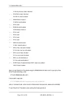
Page 237: ...ate Enterprise MIB Structure 183 Software System Firmware upgrading 175 Software Version 68 Source file bytes read 169 Specifications 3 AC Power Supply 5 Chassis 3 Code Out 8 Environmental 4 GPS Reference 4 GPS Time and Frequency Referenc 16 J1 Optional TI ET 6 8 J2 Optional Programmable Pulse Out PPO 7 J2 Rate Out 7 J3 Optional Frequency Measurement 7 Network Port 10 100 6 RS 232 RS 422 Interface...

Page 238: ...Display 38 41 Subnet Mask 111 Summary of Options 16 T Test Procedure 193 TIET 128 Time Quality Setup 56 Time Date 52 Time Code J1 Input 128 Time Display 37 41 Configuring 30 Time Error 67 Time Interval Event Time 128 Time Mode 90 Time On Request 62 Time Output Format 64 Time Zone 48 202 098 00116 000 Rev A Page 220 of 221 ...
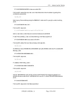
Page 239: ...ing F100 Config 171 V Version Software 68 Volatility Statement 19 X XL GPS Configuration 192 Main Card Group 188 Overview 1 Product Description and Features 1 Rack Mounting 33 Software 107 System Group 185 System Status Group 187 Traps 188 XL GPS Generated Messages 167 XYZ coordinates 72 Page 221 of 221 098 00116 000 Rev A ...

Reviews: