3
TimeSource 3000
59
Installation
097-72000-02 Issue 6: October 2003
2
5
3
S
S
S
S
S
S
S
S
S
S
S
S
S
S
S
S
S
S
S
S
S
S
S
S
S
S
S
S
S
S
S
S
S
S
S
S
S
S
S
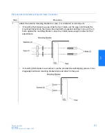
With ground rod:
Solder the connection to the 6 AWG frame ground rod that is run vertically on each side of
the rack, if provided. Two methods are acceptable:
•
Crimp an appropriate-size spade lug to the 16 AWG wire, bend the lug around the 6
AWG rod, and solder.
•
Strip enough insulation from the 16 AWG wire to permit three complete turns
around the 6 AWG rod and solder.
Note:
When soldering, use a 25 watt soldering iron to ensure the 6 AWG rod is heated
sufficiently to prevent a cold solder connection
.
Without ground rod:
Crimp the supplied spade lug to the 16 AWG wire, and screw the lug to a screw hole on the
rack. Remove the paint and sand the area around the screw hole to ensure proper
conductivity. Coat the connection with an electrically conductive antioxidant compound, for
example, Kopr-Shield spray.
Crimp the supplied spade lug to the other end of the 16 AWG wire, and connect it to the
FRM terminals on TB1 and TB2 (Figure 12).
Summary of Contents for TimeSource 3000
Page 1: ...TimeSource 3000 GPS Primary Reference Source 097 72000 02 Issue 6 October 2003 ...
Page 47: ...3 Chapter Installation This chapter provides the steps required for installation and power up ...
Page 107: ...Chapter 4 TL1 Reference This chapter provides information for using the TL1 language ...
Page 203: ...Chapter 6 Specifications This chapter provides equipment specifications ...

