background image

MoniCom


WWW.SYMCOD.COM


How to install your MoniCom


The support provided with the MoniCom permits to install the unit on a wall or on a table.  Once fixed, 

the angle of the MoniCom can be easily adapted to the needs of each user, no need to do a new adjustment 
of the screws (see 

 fixation & handling) 


How to install the MoniCom 


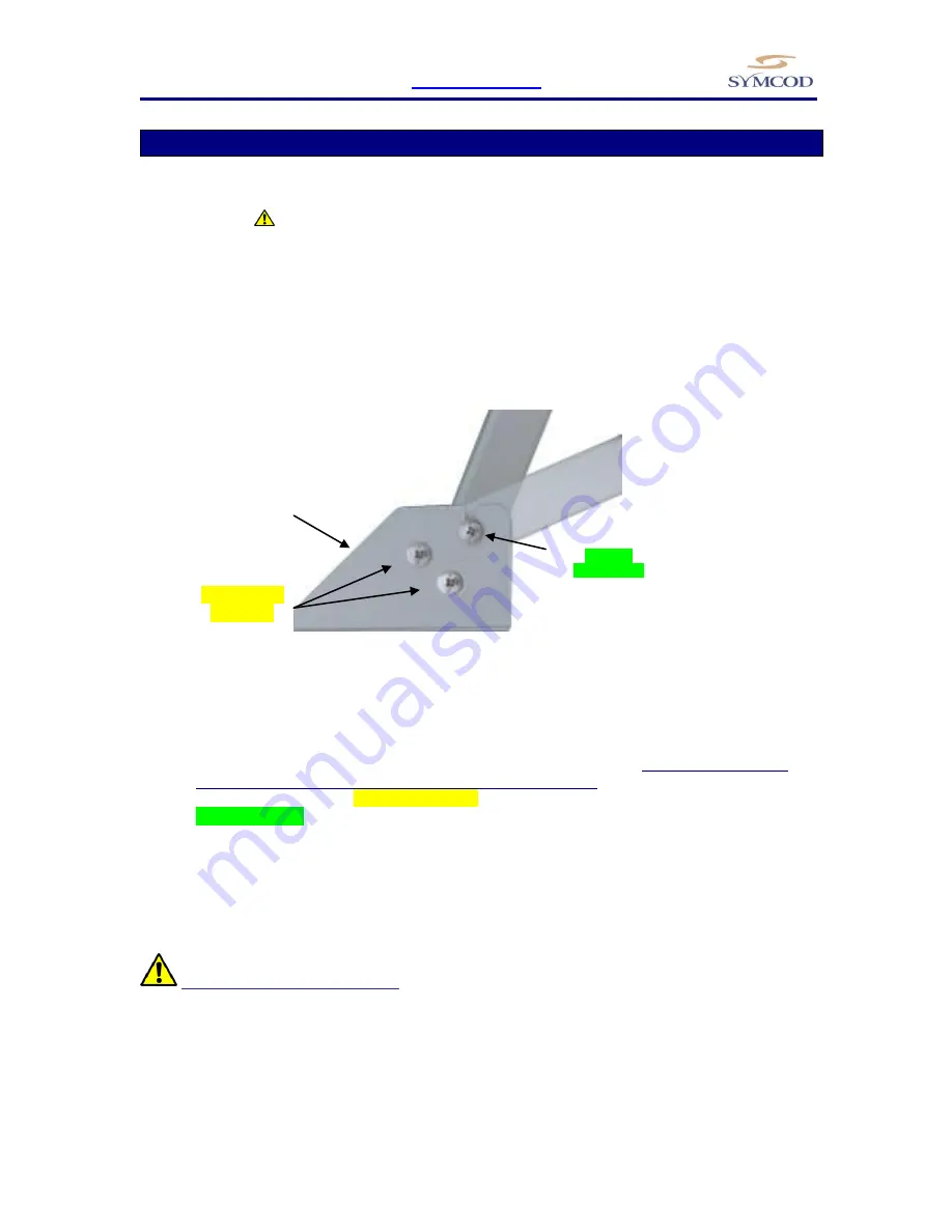
Figure 1 

Base support MoniCom 

Side view 


1.


Determine the appropriate emplacement (plane & motionless surface).  

Be sure to choose a fixed 

and solid plane surface able to support the weight of the MoniCom.


2.


On the base support (D), completely unscrew screw A (wall mount) or the screw B (desk top).  
Partially unscrew the screw C (see figure 1).   

3.


Separate the base support (D) from the MoniCom. 


Fix the base support (D) at the chosen emplacement. 


Replace MoniCom on its base support in the desired position (Wall mount or desktop) 
and fix the corresponding screw, A for wall mount, B for desktop. 


Tighten the screws on each side of the base support. 


 WARNING: fixation & handling 


Choose  a  fixed  and  solid  plane  surface  able  to  support  the  weight  of  the  MoniCom  (15"= 

approximately 9.4 lbs / 4.26Kg, 19"= approximately 15.5 lbs / 7 Kg).  Handle the MoniCom safely in 
order to avoid any back wound. 


Wallmount 
position  

Desktop  
position 

Completely 

unscrew  

Partially 

unscrew (C)  

(A)  Wallmount 

screw 

(B) Desktop screw 

OR 

(D) Base support 

Summary of Contents for MoniCom 15''

Page 1: ...MoniCom 15 and 19 User Manual Documentation Version 27 09 2012 WEB site www symcod com E mail support symcod com...

Page 2: ...tions Failure of owner to perform periodic product maintenance as stated in documents supplied Any other cause which does not relate to a product defect Damage caused by static Removal installation fr...

Page 3: ...relating to this product By carrying out the installation and the use of this equipment you are presumed having read all the safety warnings WARNING Safety and reliability SYMCOD Inc will not be respo...

Page 4: ...ion in a few minutes A VESA mounting is also available to adapt to a compatible arm or to install a Thin Client box that uses this standard The Ultra Resistant touch screen is offered for usage in env...

Page 5: ...ents with very abrasive dust screen covered with a fine layer of tempered glass allows operation with deep scratches Environmental specifications 1 The casing is not designed to be watered However the...

Page 6: ...ents with very abrasive dust screen covered with a fine layer of tempered glass allows operation with deep scratches Environmental specifications 1 The casing is not designed to be watered However the...

Page 7: ...MoniCom WWW SYMCOD COM 7 Dimensions in inches for the 15 and 19 Top view Top view Wall mount Side view Wall mount Side view Desktop mount Side view Desktop mount Side view MoniCom 15 MoniCom 19...

Page 8: ...rce Plug the unit only when the installation is completed WARNING earth ground Make sure that the MoniCom case is properly grounded Options description Orientation of Connectors Because every installa...

Page 9: ...tely unscrew screw A wall mount or the screw B desk top Partially unscrew the screw C see figure 1 3 Separate the base support D from the MoniCom Fix the base support D at the chosen emplacement Repla...

Page 10: ...possible to change the location and position of the support to respond to different needs Here are some examples of mounting variants If the support provided with the unit doesn t fit your needs you...

Page 11: ...lation to a VESA mounting arm These mounting holes accept M4 screws not included that must not exceed a depth of 1 25 4mm The VESA mounting can also be used to install a Thin Client device since some...

Page 12: ...ed SVGA Allows to connect to the SVGA port of a computer SVGA cable included USB Allows to connect the touch screen to the USB port of a computer USB cable included The driver must be installed on the...

Page 13: ...and power cable to prevent them from disconnecting unexpectedly To tie your USB cable use one of the screws from the USB connector to hold the bracket in place connect your USB cable then tie it to t...

Page 14: ...the instruction manual The use of this equipment is not planned for a residential use Service and support Support Please use EMAIL for your requests For technical questions hardware and software emai...

Reviews: