


www.symc-tec.com
The Chapter Two Software Operation Instruction
10
2.7 Position
“Calc” This is the calculated position based on the number of steps
“Enc” This is the feedback position of encoder assuming one is attached
“Zero” This button sets the current position to zero for both the calculated and encoder
reading
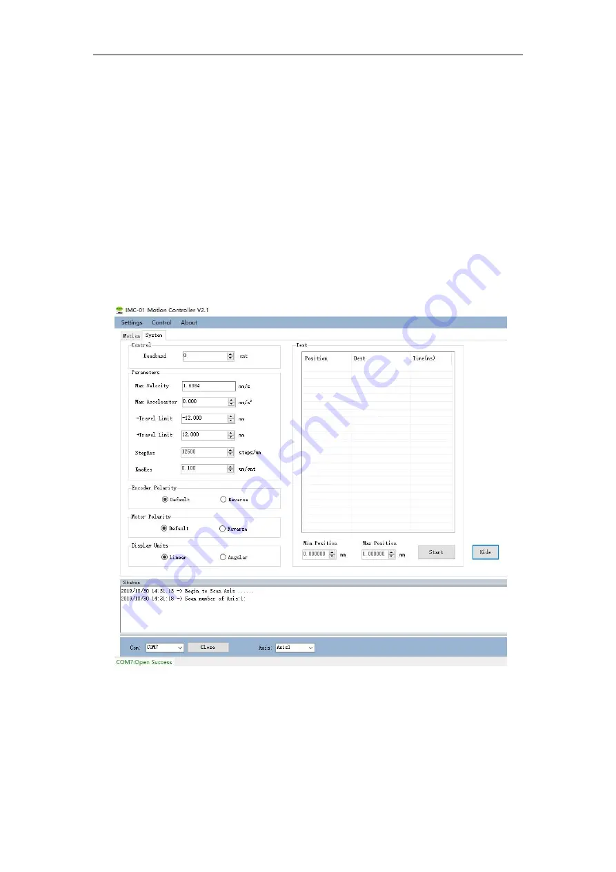
2.8 System Interface
This section allows you to set motion parameters, encoder polarity,motor polarity and loop
motion between two positions etc.
Fig 2.5
“
System
”
interface
“Deadband” This setting changes the amount of error the closed loop control mode will
allow before trying to reposition
“Max Velocity”- Maximum allowed Velocity
“Max Acceleartor” - Maximum Allowed Acceleration
“-Travel Limit” - The soft travel limit in the negative direction


