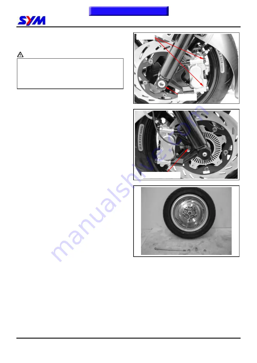
background image


15-5 


Front Wheel 

Loosen 2 bolts from the front brake caliper and 
remove it 

 Caution


  Care shall be taken not to push the brake 

lever to avoid the brake pad being squeezed 
out. In case that the brake pad is accidentally 
squeezed out, use a screwdriver to force it 
back to the place. 


Loosen screw & remove speedometer cable. 
Turn loose the axle nut. 


Pull out the front wheel axle. 
Remove the front wheel and both side collar.


2 screws 


To this chapter contents 

Axle nut 

Speedometer cable 

Summary of Contents for MAXSYM 400i

Page 1: ...MAXSYM 400i 400i ABS 600i ABS SERVICE MANUAL 201404 FOREWORD HOW TO USE THIS MANUAL CONTENTS MECHANISM ILLUSTRATION...

Page 2: ...rvice Procedures Operation Key Points and Inspection Adjustment so that provides technician with service guidelines If the style and construction of the motorcycle MAXSYM 400i 400i ABS 600i ABS are di...

Page 3: ...stem information There are 4 buttons Foreword Contents How to Use This Manual and Mechanism Illustration in the PDF version and can be access to these items by clicking on the buttons If user wants to...

Page 4: ...7 8 Cylinder Piston 7 8 1 8 14 V Belt Drive System 8 9 1 9 8 Final Drive Mechanism 9 10 1 10 4 AC Generator Starting Clutch 10 11 1 11 8 Crankshaft Crankcase 11 12 1 12 12 Cooling System 12 13 1 13 1...

Page 5: ...itch Dimmer winker horn seat open pass switch Muffler Reserve tank cap Coolant filler cap Main switch Fuel tank fuel pump Side stand Back mirror Headlight Front brake lever Rear brake lever Home page...

Page 6: ...Engine oil Limits to use SAE 10W 30 API SG class oil Warranty will not cover the damage that caused by not apply with the limited engine oil Recommended oil KING MATE G 3 oil Grease King Mate G 3 is...

Page 7: ...efore performing service work on these parts wear the heat insulation gloves or wait until the temperature drops Battery Caution Battery emits explosive gases flame is strictly prohibited Keep the pla...

Page 8: ...most of the cleaning agents have bad effect on them Never bend or twist control cables to avoid unsmooth control and premature worn out Rubber parts may become deteriorated when old and be damaged by...

Page 9: ...se install the oil seal with the name of the manufacturer facing outside and check the shaft on which the oil seal is to be installed for smoothness and for burrs that may damage the oil seal Remove r...

Page 10: ...ative cable firstly Notre tools like open end wrench do not contact with body to prevent from circuit short and create spark After service completed make sure all connection points is secured Battery...

Page 11: ...se Check if the connector is covered by the twin connector boot completely and secured properly Before terminal connection check if the boot is crack or the terminal is loose Insert the terminal compl...

Page 12: ...ht nor have excessive slack Protect wires or wire harnesses with electrical tape or tube if they contact a sharp edge or corner Thoroughly clean the surface where tape is to be applied Secure the rubb...

Page 13: ...parts in all steering positions Before operating a test instrument operator should read the operation manual of the instrument And then conduct test in accordance with the instruction With sand paper...

Page 14: ...Reduction Gear Engine Type 4 STROKE ENGINE Clutch Centrifugal dry type Installation and arrangement Vertical below center incline 80 Transmission CVT Fuel Above 92 unleaded Speedometer 0 180 km hr Cy...

Page 15: ...y Reduction Gear Engine Type 4 STROKE ENGINE Clutch Centrifugal dry type Installation and arrangement Vertical below center incline 80 Transmission CVT Fuel Above 92 unleaded Speedometer 0 180 km hr C...

Page 16: ...r head side cover bolt 2 6 1 0 1 4 Cylinder head cover bolt 4 6 1 0 1 4 Cylinder head stud bolt inlet pipe 2 6 1 0 1 4 Cylinder head stud bolt EX pipe 2 8 2 4 3 0 Air inject pipe bolt 4 6 1 0 1 4 Air...

Page 17: ...4 10 3 5 4 5 Rear cushion upper connection bolt 1 10 3 5 4 5 Rear cushion under connection bolt 1 8 2 4 3 0 Rear fork mounting bolt 2 10 4 0 5 0 Brake hose bolt 2 10 3 0 4 0 Brake air bleeding valve 1...

Page 18: ...tor is sufficient The fuel injector is not supplied with sufficient fuel 1 Check the fuel amount in the fuel tank 2 Check if the fuel pipe and the vacuum tube are blocked or not 3 Malfunction of fuel...

Page 19: ...Abnormal compression pressure 1 Worn out cylinder or piston ring 2 Cylinder gasket leakage 3 Sand hole in compression parts 4 Valve deterioration 5 Jammed piston ring Check if the fuel injector is clo...

Page 20: ...ark Poor spark Remove the spark plug and check the spark condition Check the fuel pump supply condition Good Poor Normal Clogged 1 Replace the fuel injector 1 Incorrect ignition timing malfunction of...

Page 21: ...maged drive belt 2 Damaged movable drive face 3 Damaged driven face spring 4 Broken clutch weight 5 Broken drive shaft groove 6 Worn out or damaged transmission gear Engine shuts down or trembles when...

Page 22: ...ormation 1 17 Lubrication Points Steering stem bearing Seat locker Rear wheel bearing Main stand pivot Side stand pivot Front wheel bearing Acceleration cable Front rear brake lever pivot To this chap...

Page 23: ...1 General Information 1 18 NOTE To this chapter contents...

Page 24: ...2 0 5 L Engine Oil capacity 2 000 c c 2 300 c c change with oil filter replaced 1 900 c c 2 000 c c change 1 800 c c 1 900 c c Transmission Gear oil capacity 350 c c change 330 c c Capacity of coolan...

Page 25: ...nections in cooling system I I 31 Coolant reservoir I I 32 Coolant I R 33 ECU input voltage I 34 EFi sensor coupler I Code I Inspection cleaning and adjustment R Replacement C Cleaning replaced if nec...

Page 26: ...After draining make sure washer can be re used Install oil drain bolt Torque value 3 5 4 5kgf m Add oil to crankcase oil viscosity SAE 10W 40 Recommended using King serial oil Engine oil capacity Dis...

Page 27: ...emove luggage box Remove rear carrier Remove body covers Check all lines and replace it when they are deteriorated damaged or leaking Warning Gasoline is a low ignition material so any kind of fire is...

Page 28: ...ment nut Tighten the fixing nut and check acceleration operation condition Air Cleaner Air Cleaner Element Remove 6 screws from the air cleaner cover Remove the air cleaner element Caution The air cle...

Page 29: ...inder head cover side cover Remove ignition timing hole cap located in front upper side of engine right cover Turn camshaft bolt in C W direction and let the T mark on the camshaft sprocket aligns wit...

Page 30: ...ure spark plug gap Spark plug gap 0 6 0 7 mm Carefully bend ground electrode of the plug to adjust the gap if necessary Hold spark plug washer and install the spark plug by screwing it Tighten the plu...

Page 31: ...r head leaking piston piston ring and cylinder worn out If the pressure is too high it means carbon deposits in combustion chamber or piston head Drive Belt Remove mounting bolt located under air clea...

Page 32: ...the motorcycle with poor cushion Looseness wear or damage cushion will make poor stability and drive ability Front cushion Press down the front cushion for several times to check it operation Check if...

Page 33: ...e brake fluid together Filling Out Brake Fluid Tighten the drain valve and add brake fluid Operate the brake lever so that brake fluid fulfilled inside the brake system hoses Added Brake Fluid Add bra...

Page 34: ...ke lining Remove the brake clipper bolt and take out the clipper Caution Do not operate the brake lever after the clipper removed to avoid clipping the brake lining Pry out the brake lining with a fla...

Page 35: ...ngine Appointed tire pressure Tire size Front tire Rear tire Tire pressure as cold engine Kg cm Load for under 90 Kg 2 00 2 25 Full loaded 2 00 2 50 Check if tire surface is stuck with nails stones or...

Page 36: ...verse procedures of removal Caution If there is rust on the posts very serious spray some hot water on the posts Then clean it with steel brush so that can remove rust for more easily Apply some greas...

Page 37: ...spring compressor NAME Tappet adjusting wrench NAME Oil seal driver 45 65 10 NO SYM 2301000 L4A NO SYM 9001200 NO SYM 9125500 L4A NAME Crank Shift Oil Seal Driver 35 55 7 NAME PULLEY DRIVEN FACE OPENE...

Page 38: ...AME AC G FLYWHEEL PULLER NO SYM 9020200 NO SYM 2210100 NO SYM 3110000 HMA NAME Final shaft bearing installer NAME Water pump bearing installer NAME Balance shaft bearing installer NO SYM 9615000 L4A A...

Page 39: ...SYM 9100310 L4A L6C NO SYM 9100310 L4A L6C NO SYM HT07010 NAME Vacuum pressure gauge NAME Cylinder pressure gauge NAME Vehicle circuit test tool kit NO SYM HT07011 NO SYM HT07008 NO SYM HE170008 NAME...

Page 40: ...Oil Oil viscosity SEA 10W 40 Recommended King serial oils Gear oil Gear oil viscosity SEA 85W 140 Recommended SYM Hypoid gear oils Items Standard mm Limit mm Oil pump Inner rotor clearance 0 15 0 20 C...

Page 41: ...Kgf m Fill out engine oil oil viscosity SEA 10W 40 Recommended using King serial oil Install dipstick start the engine for running several minutes Turn off engine and check oil level again Check if e...

Page 42: ...and take out oil pump driving chain and sprocket Torque value 0 8 1 2 Kg m Make sure that pump shaft can be rotated freely Remove 3 bolts on the oil pump and then remove oil pump Oil Pump Disassembly...

Page 43: ...arance between inner and outer rotors Limit 0 20 mm Check clearance between rotor side face and pump body Limit 0 12 mm Oil Pump Reassembly Install inner and outer rotors into the pump body Align the...

Page 44: ...be rotated freely Oil Pump Installation Install the oil pump and then tighten bolts Torque value 0 8 1 2 Kg m Make sure that oil pump shaft can be rotated freely Install oil pump driving chain and sp...

Page 45: ...ange Remove oil level inspection bolt Remove drain plug and drain oil out Install the drain plug after draining Torque value 1 0 1 4 Kgf m Make sure that the drain plug washer can be reused Add oil to...

Page 46: ...ng Procedure 4 36 Air Cleaner 4 39 EFi System Diagnosis Methods 4 40 Check Light Flault Codes Differentiation 4 41 Fault Code And Sensors Table 4 42 Fault Code and Check Light Flashing Lighting Identi...

Page 47: ...tem 4 2 EFi System Vehicle Configuration Rollover sensor ECU CPS O2 Sensor Fuel pump Right TW Sensor Diagnostic coupler Test switch TA Sensor AISV EFi Check light Left TPS ISC To this chapter contents...

Page 48: ...O2 Sensor Roll Over Sensor Throttle Position Sensor Manifold Absolute Pressure Sensor Crankshaft Position Sensor INJECTOR IGN COIL FUEL PUMP CHECK LIGHT Tuning tools Diagnostic tool VBATT Battery Volt...

Page 49: ...ing fuel and air Under this condition three major processes are done simultaneously in the carburetor 1 Air quantity measurement 2 Fuel quantity determination 3 Mixing of fuel and air Electronic Fuel...

Page 50: ...sly which may lead to lack of battery power less than 10 V and the fuel pump will not be able to operate The correct way is to use a new battery Injector Eight hole type injector provides two intake v...

Page 51: ...the engine achieve the maximum power output but also help improve fuel consumption rate Specifications 1 Ignition timing BTDC 10 1550RPM 2 Spark plug NGK CR8E Clearance 0 6 to 0 7 mm 3 ACG crankshaft...

Page 52: ...The magnetic field type sensor generates a voltage signal to calculate engine speed with ACG gear ring 18 1 tooth There is one tooth every 20 degree on the gear ring But one of the teeth is blank for...

Page 53: ...en the temperature falls Sensors provide the temperature of the engine coolant and intake air to ECU to determine the injection and ignition timing Manifold absolute pressure sensor Manifold absolute...

Page 54: ...uel mixture with higher temperature and higher NOx concentration 1 O2 Sensor outputs feedback signal to ECU which keeps the air fuel mixture near the stoichometric ratio approximately 14 6 and forms t...

Page 55: ...ted both electric resistance and voltage value change determining the throttle position Function TPS determines the throttle valve position and sends signal to ECU as reference of engine control TPS E...

Page 56: ...Idle Speed Control Valve ISC stepper motor Function ECU controls ISC stepper motor to adjust the bypass intake air quantity and stabilized the idle speed ISC ECU Battery Va Va Vb Vb Step S N S S N N V...

Page 57: ...iate air quantity to reduce pollutant emission Basic Principle When the engine RPM and throttle opening are higher than the default value ECU controls AISV opening or closure AISV Reed valve Fresh air...

Page 58: ...el from splashing Cautions Do not bend or twist the throttle cable Damaged cable will lead to unstable driving When disassembling fuel system parts pay attention to O ring position replace with new on...

Page 59: ...vehicle 2 Key on but not to start engine confirm ECU and the diagnostic scanner can be connected or not 3 Diagnostic scanner will automatically display Version certification of the screen 4 Confirm t...

Page 60: ...opening immediately Throttle valve positioning screw has been adjusted and marked on the production line Readjustment is not suggested Treatment of abnormal phenomena If all fuel injection associated...

Page 61: ...ltage Voltage meter negative access to the inlet pressure sensor third pin Green Red Voltage meter positive access to the inlet pressure sensor first pin Yellow Black 5 Confirmed plains output voltage...

Page 62: ...e ECU then calculated the temperature and in accordance with the ECU temperature and state amendments injection time and ignition angle Testing Procedures Resistance Value Measurement Dismantled inlet...

Page 63: ...using the probe tool or can be removed connector to voltage measurements direct measurement 2 Opened the main switch but do not to start engine 3 Use voltage meter DC stalls DCV to check sensor volta...

Page 64: ...osis tool screen switches to a data analysis 01 03 screen 3 Rotations throttle and check voltages Treatment of abnormal phenomena Throttle sensor damage or connector poor contact Check whether the abn...

Page 65: ...age signals sent to the ECU was calculated engine temperature ECU accordance with the engine warm up to amendment the injection time and ignition angle Testing Procedures Dismantled engine temperature...

Page 66: ...oved O2 Sensor and the wire harness between the coupler Open the main switch but not to start engine Use voltage meter DC stalls DCV to check inlet pressure sensor voltage Confirmed working voltage Vo...

Page 67: ...engine speed to about 4500 rpm Observation O2 Sensor actuator circumstances Observation O2 Sensor voltage values that the situation changes Detection judge Working voltage value above 10V Resistance v...

Page 68: ...the electronic control agencies not against removed after a single measurement Normal state after power is turned on the main switch measurement of ECU power relays red yellow line to the Green Line...

Page 69: ...ce values A phase ISCAP and ISCAN B phase ISCBP and ISCBN Inspection of the actuation testing can only be on engine not a single test Closure of the main switch Use hand to touch Idle Air Control Valv...

Page 70: ...mp to damage it and the fuel injector Testing Procedures 1 Fuel pump working voltage confirmed Fuel pump coupler to properly using the probe tool or can be removed coupler working voltage measurements...

Page 71: ...re measurement will go to the demolition of the fuel hose such as injector or fuel pump hose hydraulic measurements after be sure to confirm whether there is a leakage of fuel situation in order to av...

Page 72: ...tightly by hands fuel spills should not be the case Key on and start the engine injector injection state examination Detection judge 1 Between the two pin resistance values 10 5 0 53 2 injection stat...

Page 73: ...e Ignition coil primary circuit 2 8 15 20 C Treatment of abnormal phenomena 1 Ignition coil internal coil disconnection damaged or plugs bad contact 2 Ignition coil ignition is not abnormal proposes t...

Page 74: ...or closing Testing Procedures Resistance Confirmation Use of the meter Ohm stalls measurement of the secondary air injection solenoid valve resistance value Detection judge Resistance value 26 2 6 20...

Page 75: ...4 Fuel Injection System 4 30 EFi System Circuit To this chapter contents...

Page 76: ...P L Y CRANK PULSE SENSOR 13 14 TA G BR AIR TEMP SENSOR 15 TEST P W TEST SW 16 INJ L G INJECTOR 17 18 MIL Y G MULTI INDICATOR LAMP 19 FLPR O W FUEL PUMP RELAY 20 ISCBP G B IDLE SPEED CONTROL B 21 ISCAP...

Page 77: ...hin ECU 5V voltage sensor voltage of less than 0 2 V 1 Main switch OFF 2 Use probe inserted throttle sensor engine temperature sensor the inlet pressure sensor power connector 3 Main switch ON 4 Use v...

Page 78: ...hooting 1 Fuel tank inadequate 2 Fuel injector pressure less than 294 6kpr 3 Pipeline fuel spills 4 Pressure Regulating Valve anomaly 5 Fuel pump pipe leakage 6 Fuel pump anomaly 7 Fuel injector anoma...

Page 79: ...ecommended that engine checks whether there are other traditional institutions abnormal Idle flameout 1 Link diagnosis tool to view EFI fault content 2 In accordance with Troubleshooting procedures on...

Page 80: ...reen EFi system more relevant institutions each recognized by the detection if still unable to rule out the idling flameout problem it is recommended that engine checks whether there are other traditi...

Page 81: ...nspection NO Injector whether injection Injector spray angle is normal Fuel pressure enough Removed the injector on the intake manifold but not removal of harness coupler Injector and injector cap tig...

Page 82: ...NG YES Use diagnosis tool to detect of the manifold pressure Engine vacuum Diagnosis tool manifold pressure for compliance with specifications Valve clearance is not normal Intake system leak Manifold...

Page 83: ...the fuel tank Remove Install fuel pump and fuel unit Remove fuel pump fixed bolts Bolt 6 remove fuel pump Install In the anti demolition order Cautions Then remove fuel pump fuel in fuel tank internal...

Page 84: ...leared please new replacement Cautions Air cleaner filter for paper products must not soak or cleaning by water Install air cleaner element Install In the anti demolition order Cautions Air cleaner fi...

Page 85: ...Diagnosis tool will connect to the motorcycle for coupler diagnosis according to the use of diagnostic tool testing methods when belong fuel injection system fault or parts fault according to the diag...

Page 86: ...Fault Code the implementation of the following steps 1 Main switch OFF 2 Cross access the test switch for interconnection access and without opening up cross access movement must indeed 3 Full throttl...

Page 87: ...sensor fault TA Sensor and wire 6 1630 Roll over sensor fault Roll over sensor and wire 7 0130 O2 sensor fault O2 Sensor and wire 8 0201 1 fault Injector and wire 9 0351 IG 1 fault Ignition coil and...

Page 88: ...rocedures Please refer to the EFI System components description O2 sensor chapter 8 0201 1 fault lighting long 3 short 3 Injector and wire Fault detection procedures Please refer to the EFI System com...

Page 89: ...button into the main screen there are 6 major functions ECU ID DATA STREAM FREEZED DATA TROUBLE CODE ERASE TB CODE and CO ADAPTION 5 Use select button under the function press the ENTER button access...

Page 90: ...N 3 Open the diagnosis left power switch which turn on the LCD screen the screen brightness adjustment knob to the appropriate brightness 4 SYM and cartridge content display on screen such as icon by...

Page 91: ...ional areas 1 ECU ID 2 DATA STREAM 3 FREEZED DATA 4 TROUBLE CODE 5 ERASE TB CODE 6 CO ADAPTION Use button select mobile anti white subtitles implementation of the project and then press the ENTER key...

Page 92: ...buttom to the implementation of information systems function ECU ID containing two functions 1 1 ECU ID Datas 1 2 ECU Pin Assign 1 1 ECU ID Datas Use button select ECU ID projects press the ENTER butt...

Page 93: ...Pin Assign Use button select the ECU pin project and press the ENTER button to the implementation of the ECU pin functions ECU pin assign total of 5 pages that can be used left and right button view t...

Page 94: ...tton select DATA STREAM project press the ENTER key to the implementation A total of 3 pages are able to use left and right button view injection system information On the any screen press the EXIT bu...

Page 95: ...ltage O2 SENSOR mV Idle 50 200mV O2 sensor voltage O2 HEATER Idle 3500rpm ON O2 heater actuator state ENGINE TEMP C Stable 85 95 C Engine temperature cooling water temperature In the DATA STREAM of th...

Page 96: ...CRANKSHAFT Idle CW Crankshaft functioning direction TEST TERMINAL Idle OPEN Test terminal state IDLE SET RPM 1650 RPM Idle speed goal set value ISC STEP Idle 75 95 Idle Air Control Valve stepper motor...

Page 97: ...r learning step In the DATA STREAM of the screen use button to move the left side of the project symbol selected items press the ENTER button lock of the project and press the F4 button showed that th...

Page 98: ...press the ENTER key to the implementation Only one page at any screen press the EXIT button the function can return to the directory screen In the FREEZED DATA of the screen use button to move the le...

Page 99: ...that showing System is OK Press the EXIT button the function can return to the directory screen If the system has faulty code that is showing the fault code that can be used left and right or button...

Page 100: ...TB CODE project press the ENTER key to the implementation Conditions The main switch ON or in the engine running state the fault code can be removed Fault code removed namely showing the ERASE TB SUC...

Page 101: ...select CO ADAPTION project press the ENTER button into the CO adjustment screen Use left and right or button CO value can be adjusted CO ADAPT CO adjusted value CO Read CO read back value Press the EX...

Page 102: ...mooth Inability and slow Flameo ut Idle flameout Acceleratio n flameout Related spare parts Roll over sensor Fuel pump Ignition coil Inlet pipe Injector O2 sensor Power relay Fuel pressure adjustment...

Page 103: ...s tool Manifold pressure 32 38kPa Valve clearance abnormal Intake system leak 5 Injection state The injector removed from the throttle body but not dismantle pipeline Main switch ON but not start engi...

Page 104: ...4 Fuel Injection System 4 59...

Page 105: ...gear reduction mechanism Specification Item Capacity LX40A LX60A Engine oil capacity Replacement 1800 c c 1900 c c Disassembly oil filter replaced 1900 c c 2000 c c Disassembly 2000 c c 2300 c c Gear...

Page 106: ...seat dampers Remove the air box cover Disconnect the air temperature sensor coupler Remove the air box Disconnect the starter motor wire Remove the spark plug cap Starter motor wire Air temperature s...

Page 107: ...m tube and throttle valve wire from the throttle body Disconnect the EFi system coupler Remove water hose from water pump Remove the thermo sensor wires l Remove the muffler 3 bolts 2 nuts Water pump...

Page 108: ...shock absorber for damage Install engine in the reverse procedures of removal Caution Pay attention of foot hand safety as engine installation to avoid hurting Do not bend or twist wires Cables wires...

Page 109: ...5 ENGINE REMOVAL 5 5...

Page 110: ...assembly 6 6 Cylinder Head Inspection 6 8 Valve Stem Replacement 6 10 Valve Seat Inspection and Service 6 11 Cylinder Head Reassembly 6 13 Cylinder Head Installation 6 14 Valve Clearance Adjustment 6...

Page 111: ...030 Clearance between valve stem and guide Intake 0 010 0 037 0 080 Exhaust 0 030 0 057 0 100 Free length of valve spring Inner 33 700 Outer 38 800 Valve seat width 1 000 1 6 Tilt angle of cylinder h...

Page 112: ...test and judging the abnormal noise generated Low compression pressure 1 Valve Improper valve adjustment Burnt or bent valve Improper valve timing Valve spring damage Valve carbon deposit 2 Cylinder h...

Page 113: ...n remove the thermostat Remove hole bolt and spring for the cam chain tensioner Loosen 2 bolts and then remove tensioner Remove thermostat 2 bolts Remove Air Injection system AI pipe mounting bolts Re...

Page 114: ...g chain out Remove the 2 cylinder head mounting bolts from cylinder head right side and then remove 4 nuts and washers from cylinder head upper side Remove the cylinder head Remove cylinder head gaske...

Page 115: ...er SYM 1445100 Use a valve cotter remove assembly tool to press the valve spring and then remove valves Caution In order to avoid loosing spring elasticity do not press the spring too much Thus press...

Page 116: ...m seals Clean carbon deposits in combustion chamber Clean residues and foreign materials on cylinder head matching surface Caution Do not damage the matching surface of cylinder head To this chapter c...

Page 117: ...770mm EX Replacement when less than 36 400mm Inspect the camshaft bearing for looseness or wear out If any damage replace whole set of camshaft and bearing Rocker Arm Measure the cam rocker arm I D a...

Page 118: ...record each valve guide inner diameters Service limit 5 03 mm The difference that the inner diameter of valve guide deducts the outer diameter of valve stem is the clearance between the valve stem and...

Page 119: ...en pressing in the new valve guide cylinder head still have to be kept in 100 150 Adjust the valve guide driver and let valve guide height is in 13 mm Press in new valve guide from rocker arm side Too...

Page 120: ...eal is roughness wear out or incomplete contacted with valve seat Valve seat inspection If the valve seat is too width narrow or rough corrects it Valve seat width Service limit 1 6mm Check the contac...

Page 121: ...ve seat slightly press down the valve but do not rotate it so that a seal track will be created on contact surface Caution The contact surfaces of valve and valve seat are very important to the valve...

Page 122: ...alve cotter remove assembly tool to press the valve springs and then install valves Caution In order to avoid damaging the valve stem and the cylinder head in the combustion chamber place a rag betwee...

Page 123: ...er head Avoid residues of gasket or foreign materials falling into crankcase as cleaning Install 4 washers and tighten 4 nuts on the cylinder head upper side and then tighten 2 cylinder head mounting...

Page 124: ...I pipe 4 bolts Install inlet pipe onto cylinder head Install and tighten spark plug Torque value 1 0 2 0kgf m Caution This model is equipped with more precision 4 valve mechanism so its tighten torque...

Page 125: ...th feeler gauge After valve clearance had been adjusted to standard value hold adjustment bolt and then tighten the Adjustment nut Standard Value IN 0 10 0 02 mm EX 0 15 0 02 mm Install the cylinder h...

Page 126: ...recautions in Operation 7 2 Troubleshooting 7 3 Cylinder Piston Removal 7 4 Piston Ring Installation 7 7 Piston Installation 7 8 Cylinder Installation 7 8 Mechanism Diagram Home page Contents 1 0 1 4k...

Page 127: ...n ring Clearance between piston ring and ring groove Top 0 015 0 050 0 090 2nd 0 015 0 050 0 090 Piston ring end gap Too 0 150 0 300 0 500 2nd 0 300 0 450 0 650 Oil side rail 0 200 0 700 Piston O D 2n...

Page 128: ...iston pin boss 22 002 22 008 22 020 Piston pin O D 21 997 22 000 21 960 Clearance between piston and piston pin 0 002 0 014 0 020 Connecting rod small end I D 22 020 22 041 22 071 Troubleshooting Low...

Page 129: ...wel pin Clean up all residues or foreign materials from the two matching surfaces of cylinder and crankcase Caution Soap the residues into solvent so that the residues can be removed more easily Inspe...

Page 130: ...on rings Check if the piston rings are damaged or its grooves are worn Caution Pay attention to remove piston rings because they are fragile Place piston rings respective into cylinder below 20 mm of...

Page 131: ...of piston pin hole Service Limit LX40A 20 020 mm Service Limit LX60A 22 020 mm Calculate clearance between piston pin and its hole Service Limit 0 020 mm Measure the piston outer diameter Caution The...

Page 132: ...7 Cylinder Piston 7 7...

Page 133: ...arefully Place the openings of piston ring as diagram shown Caution Do not damage piston and piston rings as installation All marks on the piston rings must be forwarded to up side Make sure that all...

Page 134: ...between piston and crankcase in order to prevent snap ring from falling into crankcase as operation Cylinder Installation Clean up all residues and foreign materials on the matching surface of crankca...

Page 135: ...be taken when installing piston into cylinder Press piston rings in one by one as installation Caution Do not push piston into cylinder forcefully because piston and piston rings will be damaged Inst...

Page 136: ...7 Cylinder Piston 7 11 NOTE To this chapter contents...

Page 137: ...agram 8 1 Precautions in Operation 8 2 Troubleshooting 8 2 Left Crankcase Cover 8 3 Drive Belt 8 5 Drive Face 8 7 Clutch Outer Driven Pulley 8 10 Mechanism Diagram Home page Contents 0 7 1 1kgf m 6 0...

Page 138: ...OD of movable drive face boss 29 946 29 980 mm 29 926 mm ID of movable drive face 30 000 30 040 mm 30 060 mm OD of weight roller 19 500 20 000 mm 19 000 mm ID of clutch outer 144 850 145 150 mm 145 4...

Page 139: ...0 18 300 g 17 200 g Torque value Drive face nut 8 5 10 5kgf m Clutch outer nut 5 0 6 0kgf m Drive plate nut 5 0 6 0kgf m Special Service Tools Clutch spring compressor SYM 2301000 Inner bearing puller...

Page 140: ...lts from left side crank out cover remove it Remove left crankcase cover 8 bolts Remove 2 dowel pin and gasket Left crankcase cover install Install left crankcase cover in the reverse procedures of re...

Page 141: ...ned in smooth and silent and also check if bearing outer ring is mounted on cover tightly If bearing rotation is uneven noising or loose bearing mounted then replace it Bearing replacement Remove bear...

Page 142: ...oove as diagram shown so that the belt can be loosened and then remove the driven pulley Remove driven pulley Do not remove drive belt Remove the drive belt from the groove of driven pulley Inspection...

Page 143: ...shaft On the drive belt another end to the movable drive face Install the clutch outer and bearing stay collar Hold the clutch outer whit universal holder and then tighten nut to specified torque val...

Page 144: ...remove drive face nut Remove drive face and drive belt Remove movable drive face comp and drive face boss from crankshaft Remove ramp plate Remove weight rollers from movable drive face Crankshaft Dr...

Page 145: ...ter diameter of movable drive face boss and replace it if it exceed service limit Service limit 29 962 mm Measure the inner diameter of movable drive face and replace it if it exceed service limit Ser...

Page 146: ...pulley installation Press drive belt into pulley groove and then pull the belt onto drive shaft Install drive face washer and nut Caution Make sure that two sides of pulley surfaces have to be free of...

Page 147: ...ce tool Release the clutch spring compressor and remove friction plate clutch weight and spring from driven pulley Remove seal collar from driven pulley Remove guide pin guide pin roller and movable d...

Page 148: ...ce and the inner diameter of movable driven face Replace it if exceeds service limit Service limit Outer diameter 40 93 mm Inner diameter 41 07 mm Driven Pulley Bearing Inspection Check if the inner b...

Page 149: ...Replace it if necessary Apply with grease onto setting pins Install new clutch weight onto setting pin and then push to the specified location Apply with grease onto setting pins But the clutch block...

Page 150: ...e of inner bearing Place new bearing onto proper position and its sealing end should be forwarded to outside Apply with specified oil Install new inner bearing Caution Its sealing end should be forwar...

Page 151: ...ht into clutch spring compressor and press down the assembly by turning manual lever until mounting nut that can be installed Hold the compressor by bench vise and tighten the mounting nut to specifie...

Page 152: ...acement 9 5 Final Drive Mechanism Reassembly 9 7 Mechanism Diagram LX40A 9 Homepage Contents Final shaft Oil seal 45 65 10 Radial ball bearing 6206 UU Final gear Radial ball bearing 6205 Radial ball b...

Page 153: ...aft Oil seal 45 65 10 Radial ball bearing 6206 UU Final gear Radial ball bearing 6305 Counter gear Counter shaft Needle bearing NK22 20R Needle bearing HKS 25 33 18 Oil seal 25 40 7 Radial ball bearin...

Page 154: ...1 4 kg m Tools Special tools Bearing 6203 6004UZ driver Bearing 6204 driver Bearing 6301 driver Oil seal 27 42 7 driver Oil seal 20 32 6 driver Inner bearing puller Outer bearing puller Troubleshooti...

Page 155: ...ar box cover bolts and then remove the cover Remove gasket and dowel pin Remove drive shaft Remove final driving gear and shaft Remove countershaft and gear Final Drive Mechanism Inspection Check if t...

Page 156: ...box cover bearing as the same way above and replace it if necessary Caution Check drive shaft and gear for wear or damage Bearing Replacement Caution Remove driving shaft bearing from left crankcase u...

Page 157: ...or as operation Remove oil seal from gear box cover and discard the seal Use bearing puller to remove the final shaft bearing from the cover If the driving shaft is pulled out with its bearing then re...

Page 158: ...aft onto gear box cover and then place it to proper position Apply with grease onto new oil seal lip and then install the oil seal Tool Oil seal 20 32 6 driver Final Drive Mechanism Reassembly Apply w...

Page 159: ...sket Install gear box cover and bolts and tighten Torque value 1 0 1 4 kgf m Install driven pulley clutch outer belt Install movable drive face drive face and left crankcase Install rear wheel Add gea...

Page 160: ...10 3 Precautions in Operation 10 2 Flywheel Installation 10 7 Right Crankcase Cover Removal 10 3 A C G Set Installation 10 7 A C G Set Removal 10 3 Right Crankcase Installation 10 7 Mechanism Diagram...

Page 161: ...dures and precaution items of starter motor Specification Item Standard value mm Limit mm ID of starting clutch gear 20 026 20 045 20 100 OD of starting clutch gear 42 175 42 200 42 100 Torque value F...

Page 162: ...nd gasket A C G Set Removal Remove 2 screws from pulse generator and then remove it Remove 3 bolts from right crankcase cover and A C G set Flywheel Removal Remove the flywheel nut Install the shaft p...

Page 163: ...e cover 3 bolts Install pulse generator 2 screws Tie the wire harness securely onto the indent of crankcase Caution Right Crankcase Cover Installation Install dowel pin and new gasket Install right cr...

Page 164: ...n 11 5 Troubleshooting 11 2 Crankcase Disassembly 11 3 Crankcase Assembly 11 6 Mechanism Diagram LX40A 3 5 4 5 kgf m 1 0 1 4 kgf m 0 7 1 1 kgf m 11 Homepage Contents 1 0 1 4 kgf m 1 0 1 4 kgf m 1 1 1...

Page 165: ...ng chain it is preferably to replace crankshaft as a unit Service data Unit mm Item Standard Limit Crankshaft Connecting rod side clearance of the big end 0 100 0 400 0 600 Vertical clearance of the b...

Page 166: ...emove the water pump shaft locknut Remove the oil separator bolt x 2 Remove the oil pump drive sprocket driven sprocket and drive chain Remove the right crankcase bolts bolt x 3 Oil pump driven sprock...

Page 167: ...x 11 Remove the right crankcase from the left crankcase Remove the crankshaft and balancer shaft from the left crankcase Check the main bearing on the crankcase for any wear Replace the main bearing...

Page 168: ...ersal holder and press out the main bearing Crankshaft bearing installation Use the crankshaft main bearing holder to fasten the upper and lower main bearing Align the oil path on the main bearing and...

Page 169: ...crankcase The marks on the crankshaft and balancer shaft must be aligned Assemble the right crankcase to the left crankcase Tighten the bolts on the right crankcase Install the oil pump drive sprocke...

Page 170: ...aft Crankcase 11 7 Install the oil separator bolt x2 Tighten the bolts on the left crankcase bolt x 11 Tighten the water pump shaft locknut Install the cam chain and tensioner To this chapter contents...

Page 171: ...11 Crankshaft Crankcase 11 8 NOTE To this chapter contents...

Page 172: ...est 12 4 Radiator 12 5 Steps to fill coolant after engine service 12 7 Mechanism Diagram Radiator filler cap Radiator Thermo switch fan Thermo unit temp meter Water pump Thermostat Engine coolant outl...

Page 173: ...e to open filler cap 0 9 0 15 Kg cm Capacity of coolant Engine radiator Reservoir upper 1500c c 350c c Thermostat Begins to activate at 82 92 C Stroke 0 05 3 0mm 80 C Boiling point Not pressured 107 7...

Page 174: ...The water hose and jacket are clogged Fan motor malfunction The malfunction of the radiator filler cap The engine temperature is too low The malfunction of the water thermometer and the temperature se...

Page 175: ...gine and remove by pass pipe Check by pass hole for any bubble come out If there is no bubble emitted but only coolant flow out then joint on backflow pipe and turn off the engine Remove radiator fill...

Page 176: ...for any leakage from weld seam Blow radiator clean using compressed air If the radiator is blocked by dirt use low pressure water jet to clean it Care shall be taken when straightening the sink fan R...

Page 177: ...he cooling fun mounting bolts 3 bolts Remove thermo switch Installation Install the removed parts in the reverse order of removal Install radiator in the reverse order of removal Upon completion check...

Page 178: ...se a new oil ring and apply a coat of grease on it before installation Refill the specified coolant as necessary Steps to fill coolant after engine service 1 Open the radiator cap 2 Remove the hose fr...

Page 179: ...tion pipe and pump in high pressure air to the pipe 5 Based on the above steps coolant could be drained out Steps to fill coolant 1 Remove the tube connecting to thermostat 19320 cover Pump in high pr...

Page 180: ...12 Cooling System 12 9 2 Close the fuel tube 95001 08550 loop 3 Fill up the coolant from filler neck 19039 without interruption Close this tube To this chapter contents...

Page 181: ...cover joint until coolant come out 6 Reconnect thermostat tube 19320 to thermostat cover joint 19315 7 Loosen flange bolt 8X12 on the water pump cover 19221 for exhausting air until coolant come out...

Page 182: ...diator cap and turn on the engine Overflow is normal Continue adding water to radiator until equilibrant if the amount of water diminished 9 Maintain the liquid level in reserve tank between upper and...

Page 183: ...12 Cooling System 12 12 NOTE To this chapter contents...

Page 184: ...ner Box 13 9 Side Cover 13 11 Rear Carrier 13 12 Luggage Box 13 13 Rear Body Cover 13 14 Floor Panel 13 15 Front Fender 13 15 Mechanism Diagram FR inner box Radiator cover Meter panel Meter visor Wind...

Page 185: ...hanism Diagram Upper handle cover Right lower handle cover Right body cover Double seat Inner box lid Inner box lid stiffener LH RR grip RH RR grip Right floor panel Right side cover Rear back seat Le...

Page 186: ...13 Body Cover 13 3 Mechanism Diagram FR luggage box Under cover Rear fender Left body cover RR luggage box Rear cover Maintenance cover Left floor panel Left side cover...

Page 187: ...ke sure that each hook is properly installed during the assembly Never compact forcefully or hammer the guard and the covers during assembly Rear fender Under cover R L lower handle covers R L floor p...

Page 188: ...n the 2 screws from handle upper cover front end Loosen the 2 screws from handle upper cover rear end Remove right and left handle side cover Installation Install in reverse order of removal procedure...

Page 189: ...e the wind screen garnish Loosen 6 screws from the wind screen and remove the wind screen Loosen 4 screws from the meter visor and remove the meter visor Loosen 4 screws 2 screws on each side from the...

Page 190: ...s from the front cover upper side Disconnect the headlight foggy light and winker light couplers Remove the front cover Installation Install in reverse order of removal procedures Winker foggy light c...

Page 191: ...cover Remove reserve tank cap Loosen 4screws from right left side of the meter panel Loosen 2 screws from in side of meter panel Loosen the meter cord coupler Remove the meter panel Installation Insta...

Page 192: ...k stay Loosen 1 screw from fuse box and remove it Loosen 1 screw from main switch cap and remove the cap Loosen DC power output mounting nut and remove DC power output Loosen 1 screw from battery cove...

Page 193: ...box under side Loosen 2 bolts from inside of the inner box Disconnect the hazard light and foggy light switch couplers Remove inner box Installation Install in reverse order of removal procedures 1 bo...

Page 194: ...over Remove Loosen 2 screws from the side cover side end Loosen 2 screws from the side cover upper end Remove the side cover Installation Install in reverse order of removal procedures 1 screw 2 screw...

Page 195: ...Cover 13 12 Rear Carrier Remove Loosen 4 bolts from the rear carrier and remove it Installation Install in reverse order of removal procedures Wind screen garni screen garnish garnish To this chapter...

Page 196: ...nnect the luggage box light and switch coupler Remove the luggage box rear cover Loosen 2 bolts from luggage box front side Loosen 4bolts from luggage box rear side Remove the luggage box Installation...

Page 197: ...end of floor panel Loosen right left side and middle screws from rear side of the body cover Disconnect the tail light coupler Remove the body cover Installation Install in reverse order of removal pr...

Page 198: ...cover Loosen 4 bolts and 2 screws from floor panel Remove floor panel Installation Install in reverse order of removal procedures Front Fender Remove Loosen 4 screws from front cushion Remove the fro...

Page 199: ...13 Body Cover 13 16 NOTE To this chapter contents...

Page 200: ...ed 14 6 Front Brake Caliper 14 7 Rear Brake Caliper 14 8 Brake Disk 14 9 Master Cylinder 14 9 Anti lock Brake System 14 12 Mechanism Diagram Front master cylinder ABS controller Right front brake cali...

Page 201: ...the brake system before riding Specifications unit mm Item Standard Limit The thickness of the front brake disk 5 000 4 500 The thickness of the rear brake disk 6 000 4 500 Front and rear brake disk e...

Page 202: ...r Malfunction of the brake lever 1 Blocked brake system 2 Poor brake caliper 3 Blocked brake pipe 4 Seized worn master cylinder piston 5 Bent brake lever Uneven brake 1 Dirty brake lining disk 2 Poor...

Page 203: ...The brake pad must be replaced with new lining when it reaches the wear limit Park the motorcycle on an even ground and check if fluid level is under the LOWER mark Recommended Brake Fluid WELL RUN BR...

Page 204: ...lt in damages on painted surface such as rubber or plastic parts Remove the master cylinder cap and diaphragm Fill high quality brake fluid with same brand into master cylinder Clean the dirty brake d...

Page 205: ...tem or not If brake is still loose please bleed the system as described below 1 Tightly hold the brake lever and open the drain valve around 1 4 turn and then close the valve Caution Do not release th...

Page 206: ...the operation of brake disk Use two seal washers and hose bolts to lock the hoses and brake caliper in place Torque 3 0 4 0kgf m Refill up the brake fluid to the reservoir and make necessary air blee...

Page 207: ...5kgf m Caution Use M8 x 35 mm flange bolt only Long bolt will impair the operation of brake disk Use two seal washers and hose bolts to lock the hoses and brake caliper in place Torque 3 0 4 0kgf m Re...

Page 208: ...formance Brake lining includes the asbestos ingredient cannot use the air gun to clean it The operator should wear a mask and glove and use vacuum cleaner clean it Master Cylinder Removal Caution Do n...

Page 209: ...rake 12 645 mm Rear brake 12 645 mm Assembly Caution It is necessary to replace the whole set comprising piston spring piston cup and cir clip Make sure there is no dust on all components before assem...

Page 210: ...rake hoses with 2 new washers Tighten the brake hose bolt to the specified torque value Make sure the hose is installed correctly Install all wires hoses and components carefully to avoid twisting the...

Page 211: ...l function is identical to that of a conventional scooter The right brake lever is used for the front brake and the left brake lever for the rear brake Use of non recommended tires may cause malfuncti...

Page 212: ...ight goes on when the ignition switch is turned on and goes off shortly after the scooter speed is over 5km hr If the indicator light is on ABS may be out of function However the brake system can stil...

Page 213: ...14 Brake System 14 14 ABS control unit front view ABS control unit left rear view ABS control unit right rear view...

Page 214: ...14 Brake System 14 15 Caution Do not remove the ABS control unit coupler when the main switch is ON or the ABS control unit will be damaged Speed sensor coupler Front wheel speed sensor...

Page 215: ...System 14 16 ABS components location ABS indicator ABS control unit Front wheel detective disk Front wheel speed sensor Rear wheel detective disk Rear wheel speed sensor ABS EFi system diagnostic tool...

Page 216: ...el slip EV inlet valve for maintaining pressure keeps open and AV outlet valve for pressure reduction is closed Brake calipers receive pressure for master cylinders and brake normally Initial wheel sl...

Page 217: ...Brake pressure is reduced pulsing in the brake lever Brake caliper lowers the pressure and braking force Normal brake without wheel slip When the pressure reduction continues the wheel speed sensors...

Page 218: ...nt AV C1048 Abnormal rear AV C1059 Abnormal battery voltage over C1058 Abnormal battery voltage too low C1015 Abnormal oil pump C1033 Abnormal front wheel speed sensor hardware C1031 Abnormal rear whe...

Page 219: ...14 Brake System 14 20 NOTE...

Page 220: ...acement Air bleed 14 6 Front Brake Caliper 14 7 Rear Brake Caliper 14 8 Brake Disk 14 9 Master Cylinder 14 9 Mechanism Diagram Front brake Master cylinder 2 4 3 0 kgf m Delay valve Right front brake c...

Page 221: ...tem before riding Specifications unit mm Item Standard Limit The thickness of the front brake disk 4 000 2 500 The thickness of the rear brake disk 5 000 3 500 Front and rear brake disk eccentricity 0...

Page 222: ...of the brake lever 1 Blocked brake system 2 Poor brake caliper 3 Blocked brake pipe 4 Seized worn master cylinder piston 5 Bent brake lever Uneven brake 1 Dirty brake lining disk 2 Poor wheel alignme...

Page 223: ...must be replaced with new lining when it reaches the wear limit Park the motorcycle on an even ground and check if fluid level is under the LOWER mark Recommended Brake Fluid WELL RUN BRAKE OIL DOT 3...

Page 224: ...s on painted surface such as rubber or plastic parts Remove the master cylinder cap and diaphragm Fill high quality brake fluid with same brand into master cylinder Clean the dirty brake disk Caution...

Page 225: ...ll loose please bleed the system as described below 1 Tightly hold the brake lever and open the drain valve around 1 4 turn and then close the valve Caution Do not release the brake lever before the d...

Page 226: ...hose bolts to lock the hoses and brake caliper in place Torque 3 0 4 0kgf m Refill up the brake fluid to the reservoir and make necessary air bleeding Brake pad replacement Remove brake caliper Remov...

Page 227: ...on Use M8 x 35 mm flange bolt only Long bolt will impair the operation of brake disk Use two seal washers and hose bolts to lock the hoses and brake caliper in place Torque 3 0 4 0kgf m Refill the bra...

Page 228: ...udes the asbestos ingredient cannot use the air gun to clean it The operator should wear a mask and glove and use vacuum cleaner clean it Master Cylinder Master Cylinder Removal Caution Do not let oth...

Page 229: ...brake 13 945 mm Master Cylinder Assembly Caution It is necessary to replace the whole set comprising piston spring piston cup and cir clip Make sure there is no dust on all components before assemblin...

Page 230: ...ith 2 new washers Tighten the brake hose bolt to the specified torque value Make sure the hose is installed correctly Install all wires hoses and components carefully to avoid twisting them together C...

Page 231: ...14 Brake System 14 12 NOTE To this chapter contents...

Page 232: ...Operation 15 2 Troubleshooting 15 2 Steering Handle 15 3 Front Wheel 15 5 Front Cushion 15 8 Steering Stem 15 9 Mechanism Diagram 2 4 3 0kgf m 5 0 7 0kgf m 2 9 3 5kgf m 15 2 4 3 0kgf m 6 0 8 0kgf m 2...

Page 233: ...bearing puller SYM 6204020 Steering nut wrench SYM 6204010 Driver 32 35mm Driver 42 47mm Troubleshooting Hard to steer The steering handle stem nut is too tight The ball and the top crown of the stee...

Page 234: ...s for the master cylinder of the front brake Loosen the deceleration throttle cable fixing nut Loosen 1 screw from the acceleration throttle fixing plate Loosen 2 screws from the throttle holder Remov...

Page 235: ...handle Installation Install handle and align with bolt hole Install bolt and nut and then tighten it Torque value 4 0 5 0kgf m Apply grease to throttle cable and the sliding surface of handle Align t...

Page 236: ...id the brake pad being squeezed out In case that the brake pad is accidentally squeezed out use a screwdriver to force it back to the place Loosen screw remove speedometer cable Turn loose the axle nu...

Page 237: ...en being moved replace with a new one Caution The bearing shall be replaced in pair Wheel Place the wheel on to a rotation seat to check its rim wobbling Turn the wheel with hand and measure its rim w...

Page 238: ...Install the right side bearing Caution Carefully install the bearing in correct and evenly Bearing outer face should be faced up as bearing installation Install the brake disk and then tighten the bo...

Page 239: ...on Remove Remove front cover front under spoiler and front fender Remove three bolts at both sides Remove front wheel Remove front brake caliper Remove speedometer cable To this chapter contents 3 bol...

Page 240: ...e race body with a punch Caution Do not damage the steering stem Installation Install a new bottom cone race onto the steering stem Push the cone race until to mounted position Caution Do not tilt the...

Page 241: ...f m Caution Check the steering stem that should be rotated freely and no clearance in vertical direction Install the steering stem mounting nut and tighten the nut by means of holding the top cone rac...

Page 242: ...on the ground loosen the component 53220 HMA 00 over 1 4 turn and make the lock torque to zero 5 Start second lock procedure To begin with the component 53220 HMA 00 Make sure that the lock torque is...

Page 243: ...ism Diagram 16 1 Operational Precautions 16 2 Troubleshooting 16 2 Muffler 16 3 Rear Wheel 16 3 Rear Fork 16 5 Rear Cushion 16 6 Mechanism Diagram Home page Contents 3 5 4 5kgf m 11 0 13 0kgf m 2 9 3...

Page 244: ...uffler mounting bolt 3 2 3 8kgf m Brake clipper mounting bolts 2 9 3 5kgf m Brake disc mounting bolt 4 0 5 0kgf m Troubleshooting Run out of rear wheel Deformed or bent wheel hub Improper tires Loose...

Page 245: ...ler mounting bolt 3 2 3 8kgf m Muffler mounting nut 1 0 1 2kgf m Rear Wheel Removal Remove the exhaust muffler Remove the rear brake caliper 2 bolts and brake hose clamp 1 bolt Caution Care shall be t...

Page 246: ...l rim on a rotational support Rotate it by hand and measure the run out with a dial indicator Run out limit 2 0 mm Installation Install in reverse order of removal procedures Torque Value Rear wheel a...

Page 247: ...lock cir clip Uses the bearing driver drive out the bearing Special tool Bearing driver Install new rear fork bearing and bearing puller 6303 onto rear fork Install assembly directs puller bearing pul...

Page 248: ...shions Remove the upper bolts by left and right rear cushions and then remove the cushion Installation Install in reverse order of removal procedures Caution The rear cushion must be replaced as a uni...

Page 249: ...ter 17 21 Mechanism Diagram Home page Contents Winker Hazard control unit Spark plug A C Generator Fuse box Battery Ignition coil Main switch Reg Rec Start relay Fuel pump fuel unit Horn Passing Beam...

Page 250: ...ked with the voltmeter while charging the battery As ECU assembly does not require an ignition timing check In case ignition timing is incorrect check ECU and AC generator Verify with an ignition timi...

Page 251: ...ut of work Intermittent power supply The connector of the charging system becomes loose Poor connection of the battery cable Poor connection or short circuit of the discharging system Poor connection...

Page 252: ...harging Connect the positive terminal of the charger to the battery positive terminal Connect the negative terminal of the charger to the battery negative terminal Standard Maximum Charging current 1...

Page 253: ...17 Electrical System 17 5 Fuse Fuse circuit diagram To this chapter contents...

Page 254: ...fier Inspect the rectifier coupler to the wire harness passes the condition Item Check Points Standard Value Main switch connection R B Battery voltage ON Battery connection R G Battery voltage Chargi...

Page 255: ...and remove the negative cable terminal from the battery Connect an ammeter between the negative cable terminal and the battery negative terminal Disconnect each cable one by one and take measurement o...

Page 256: ...nnect a tachometer Turn on the headlight to high beam and start the engine Accelerate the engine to the specified revolution per minute and measure the charging voltage Specified Charging Current 1 2...

Page 257: ...17 Electrical System 17 9 ECU coupler ECU side 01 pin R Y Drive components Power 03 pin L O Crankshaft position sensor positive 09 pin G Crankshaft position sensor negative 18 pin Y G Ignition coil...

Page 258: ...rk plug Loosen 2 bolts and replace the ignition coil if necessary Inspection of crank position sensor Remove luggage box bolt 6 Disconnect the coupler of the crank position sensor and measure the resi...

Page 259: ...of Looh Looh is heard it indicates the relay is working properly Open the inner box lid and remove battery cover Disconnect the negative cable terminal of the battery Remove the luggage box Disconnec...

Page 260: ...egative terminal Check the continuity of the large terminal end If there is no continuity replace the relay Removal of Starter motor Turns off the main switch Remove the luggage box Disconnect the cou...

Page 261: ...EMP Speed sensor Turn right indicator Meter O SB L W L BR R G R G Speedometer Main switch Fuel unit Fuse 20A R Red W White B Black L Blue G Green SB Sky blue Y Yellow O Orange P Pink GR Gray BR Brown...

Page 262: ...front cover meter visor Refer chapter 14 Disconnect the coupler of the speedometer and take off the meter panel and meter Loosen 4 screws from meter panel Remove the speedometer Installation of meter...

Page 263: ...beam light Lo beam light Foggy right R Main switch Fuse 20A B Battery Winker Hazard control unit B Ignition Fuse 15A Winker switch O SB R O SB R winker indicator FR R winker light RR R winker light L...

Page 264: ...bulb with bare fingers which may create a heat point and lead to premature bulb failure Clean the fingerprint left on the bulb with alcohol Installation Install the bulb of the headlight in reverse o...

Page 265: ...stall the new main switch and tighten the mounting bolts Install the main switch coupler and cap Right handle switch Remove the handle cover and front cover Disconnect the coupler of right handle swit...

Page 266: ...tion R WR L N FROM R PUSH OFF FROM L Wire color Sky blue Gray Orange Brake Switch While grasp the brake lever firmly the terminals of white green and green yellow of the brake should have continuity R...

Page 267: ...e E position the resistance measured shall be as follows Position Resistance E Empty 90 100 F Full 4 8 Connect the wiring to the fuel unit and the ohmmeter as shown Connect the fuel unit coupler to th...

Page 268: ...e manner as described below Hang the thermo switch on the bowl filled with coolant to check the switch s opening and closing temperatures To confirm the switch is close circuited at room temperature I...

Page 269: ...il should be used as a heating medium and the test temperature must be higher than 100 Contacting the container wall by the thermometer and the thermo unit may result in wrong readings Water Temperatu...

Page 270: ...17 Electrical System 17 22 NOTE To this chapter contents...

Page 271: ...18 Wiring Diagram 18 1 18 Homepage Contents...

Page 272: ...18 Wiring Diagram 18 2...

Page 273: ...18 Wiring Diagram 18 3...

Page 274: ...18 Wiring Diagram 18 4 NOTE Homepage Contents...

Reviews: