6. CYLINDER HEAD/VALVE SYM
6-4
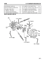
CAMSHAFT REMOVAL
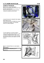
Remove the shroud of the engine.
Remove the crankcase blow-by system hose
from the cylinder head.
Remove the cylinder head bolts and then
remove the cylinder head (4 bolts).
Loosen the screw of camshaft chain adjuster
and remove O-ring.
With a flat screwdriver to tighten the screw of
camshaft chain adjuster in a clockwise
motion for release adjuster.
Turn the flywheel in counter clockwise
motion with T type wrench until the “T” mark
on flywheel aligned with the mark on the
crankcase so that the hole on the camshaft
sprocket is forward up and piston is at TDC
position.
Remove camshaft holder nut and washer.
Caution
Loosen the nuts diagonally by 2-3
sequences.
TDC mark
Hole
4 nuts
screw
camshaft chain adjuster
Blow-by hose
4 bolts
A.I
Summary of Contents for ALA125CC
Page 45: ...SYM 13 BRAKE 13 3 MECHANISM DIAGRAM Rear Drum Brake System 0 8 1 2 kgf m 0 8 1 2 kgf m...
Page 93: ......
Page 176: ...SERVICE MANUAL...


