SYM 8. V-BELT DRIVING SYSTEM/KICK STARTER ARM
8-5
Installation
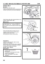
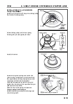
Pull out the driving pulley and then insert the
driving pulley.
Caution
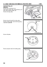
Install the clutch set with driving belt onto the
driving shaft.
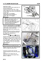
Install the sliding pulley on the other end of
belt.
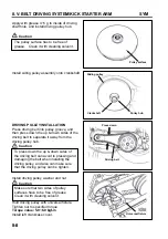
Install clutch outer.
Install the clutch with universal fixture, and
then tighten nut to specified torque value.
Torque value: 5.0~6.0 kgf-m
Caution
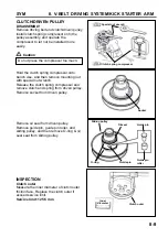
Pull out driving pulley and then insert the
driving belt into the driving pulley so that
the driving belt set can be installed onto
sliding pulley more easily.
Sliding
driven
pulley
Clutch outer
Nut
Universal fixer
When install the driving belt, if there is a
arrow mark, then the arrow mark must
point to rotation motion. If not, the letters
on the belt must be forwarded to
assembly direction.
Summary of Contents for ALA125CC
Page 45: ...SYM 13 BRAKE 13 3 MECHANISM DIAGRAM Rear Drum Brake System 0 8 1 2 kgf m 0 8 1 2 kgf m...
Page 93: ......
Page 176: ...SERVICE MANUAL...


