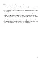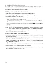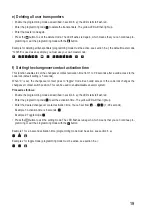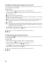
9
7. Installation and connection
Ensure that the connection cables are not kinked or squashed. This can cause malfunctions, short circuits
and device defects. Ensure that no cables or wires are damaged when drilling holes or tightening screws.
Installation and connection may only be carried out when power supply is switched off.
Make sure that the brightness sensor on the back is not exposed to light beams after installation, as switch-
ing on the system could cause activation of tamper protection with subsequent locking of all functions.
a) Installation
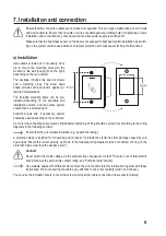
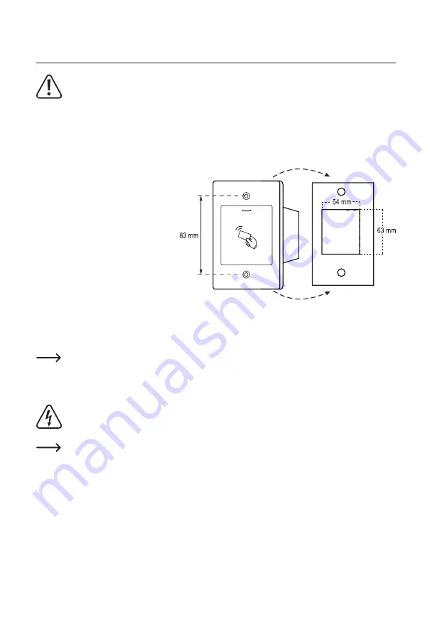
Use suitable screws and, if necessary, dow-
els to mount the mounting plate with the
module on the wall (see figure on the right)
depending on the type of wall.
The package includes two special screws
and a matching L-key. The screw head
shape provides extra protection against at-
tempted manipulations.
The included mounting frame can be pre-
installed depending on the substrate and
installation position, and the access system
should then be screwed tight.
Suitable screws and, if necessary, dowels
should be used depending on the substrate.
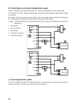
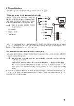
A hole for the connecting cable must be drilled before fastening. Wiring should be carried out according to the wiring
diagrams in the following sections.
Ensure that there is suitable insulation (e.g. heat shrink tubing).
A protective diode is included for connecting a door opener. It protects the electronics from damage caused by volt-
age surges. Ensure the correct polarity, as shown in the following wiring diagrams (when connected, the ring on the
protective diode must face the positive pole/+).
Caution!
Never switch the mains voltage via the potential-free changeover contact! There is a risk of fatal electric
shock! Observe the permissible contact rating; see “Technical data” chapter.
Use suitable cables with different colours. Note the colours and store this information together with these
instructions. When connecting the cables, pay attention to the correct polarity (plus/+ and minus/-).
You can use the included stickers to cover the screw openings after cable connection and successful start-up.
Summary of Contents for 2380477
Page 1: ...Operating Instructions RFID access system Item no 2380477 ...
Page 29: ...29 ...
Page 30: ...30 ...
Page 31: ...31 ...


