background image

14

b) Changing the master code

Access system programming always requires the master code, which should be selected accordingly.

The default master code is “123456” (the same applies after resetting the code lock to factory defaults). For security 
reasons, we strongly recommend that you change this master code immediately after programming when the access 
system is in normal operation.

  The master code must always consist of six digits.

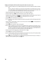
Proceed as follows:

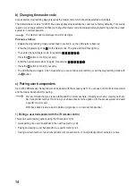
•  Enable the programming mode as described in section 8. a); the LED starts to flash red.
• 

Enter the programming code   for the master code: The yellow LED will then light up.

• 

Then enter the new master code, for example:             

• 

Press the 

 button to confirm your entry.

• 

Enter the new master code once again, for example:           

• 

Press the 

 button to confirm your entry. 

•  The LED flashes red again, which means that you can continue programming or exit the programming mode with 

the   button. 

c) Pairing user transponders

Up to 2000 different user transponders can be paired with the access system. You can use both the IR remote control 
and the master transponder for pairing.

  We recommend that you create a table and fill in all access data, including user name, memory cell num

-

ber, transponder number. This is how you can keep track of who signed up for the access system and used 

a specific memory cell.


With these data it is also easier to delete a single user or a lost user transponder.

1) Pairing a user transponder with the IR remote control

There are several pairing options using the IR remote control:

• 

Quick pairing of a user transponder in the next free memory cell 

•  Pairing and saving a user transponder in a specific memory cell
• 

Saving a certain number of user transponders with consecutive 8- or 10-digit transponder numbers at a time

Summary of Contents for 2380477

Page 1: ...Operating Instructions RFID access system Item no 2380477 ...

Page 2: ...ystem 12 9 Programming 13 a Enabling disabling programming mode 13 b Changing the master code 14 c Pairing user transponders 14 d Deleting individual user transponders 18 e Deleting all user transponders 19 f Setting the changeover contact activation time 19 g Enabling or disabling protection against incorrect entries 20 h Setting the alarm time for protection function 20 i Enabling disabling LED ...

Page 3: ... 11 Troubleshooting 25 12 Cleaning and maintenance 27 13 Disposal 27 a Product 27 b Rechargeable batteries 27 14 Declaration of Conformity DOC 27 15 Technical data 28 a Access system 28 b IR remote control 28 ...

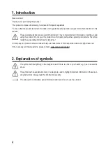
Page 4: ...ating instructions Therefore retain these operating instructions for reference All company and product names contained herein are trademarks of their respective owners All rights reserved If there are any technical questions please contact www conrad com contact 2 Explanation of symbols The symbol with the lightning in the triangle is used if there is a risk to your health e g due to an electric s...

Page 5: ...product In addition improper use can cause hazards such as a short circuit fire or electric shock Read the operating instructions carefully and store them in a safe place Only make this product available to third parties together with its operating instructions This product complies with statutory national and European regulations All company and product names contained herein are trademarks of th...

Page 6: ...cified in section Technical data and must not be exceeded Never switch the mains voltage as this can cause life threatening electric shock Always observe safety information and operating instructions for the other devices e g door opener alarm system to which the product is connected If it is no longer possible to operate the product safely stop using it and prevent unauthorised use Safe operation...

Page 7: ...mpt to recharge non rechargeable batteries as this may cause an explosion Old or depleted batteries may emit chemical liquids that cause damage to the product Therefore if the device is not to be used for a long time e g storage remove the battery from the IR remote control Leaking or damaged batteries can lead to caustic burning upon skin contact Therefore use suitable protective gloves Liquids l...

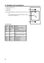
Page 8: ...ible from the outside is located right next to the LED indicator 2 Connection cables Colour Inscription Function Red 12 18 V DC Power supply 12 18 V DC Black GND GND ground Blue NO NO normally open contact of relay Brown COM COM centre contact contact of relay Grey NC NC normally closed contact of relay Yellow OPEN Door opener button White D1 Wiegand Data1 Green D0 Wiegand Data0 ...

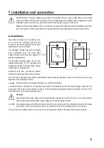
Page 9: ...llation position and the access system should then be screwed tight Suitable screws and if necessary dowels should be used depending on the substrate A hole for the connecting cable must be drilled before fastening Wiring should be carried out according to the wiring diagrams in the following sections Ensure that there is suitable insulation e g heat shrink tubing A protective diode is included fo...

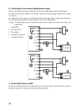
Page 10: ...oltage is missing uncommon design e g used for escape route doors which can be opened in the event of a power outage The included diode must be connected correctly near the door opener to protect the access system from voltage surges 1 Access system 2 Door opener button 3 Power adapter 4 Fail Secure door opener 5 Fail Safe door opener c Connecting to alarm system Observe the operating instructions...

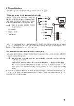
Page 11: ... one shown in the figure 2 An external card reader is connected to the access system The access system functions as a Wiegand controller and can be operated with an external card reader with 26 or 34 bit protocol automatic recognition Both card readers for 125 kHz transponders and card readers with MIFARE smart card technology 13 561 MHz are supported When a MIFARE smart card reader is used new tr...

Page 12: ... Disposal b Access system After completing the installation and connection process switch on the operating voltage The access system will emit a short beep and the red LED will light up This indicates that the access system is in standby mode You can now start programming see next chapter If the access system continuously emits beeps with the LED flashing quickly it means that the brightness senso...

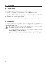
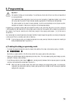
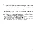
Page 13: ...nders can also be paired and or deleted with the included master transponder Anew master transponder can be saved if the one currently used is lost or defective If you no longer wish to use a master transponder for security reasons follow the procedure for resetting to factory defaults described in section 8 j a Enabling disabling programming mode To enable the programming mode enter the master co...

Page 14: ...your entry The LED flashes red again which means that you can continue programming or exit the programming mode with the button c Pairing user transponders Up to 2000 different user transponders can be paired with the access system You can use both the IR remote control and the master transponder for pairing We recommend that you create a table and fill in all access data including user name memor...

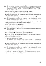
Page 15: ...programming mode with the button User transponder is assigned to a specific memory cell Although this pairing process takes more time it enables to delete a specific user transponder even when it is defective or lost Enable the programming mode as described in section 8 a the LED starts to flash red Enter the programming code to pair the transponders The yellow LED will then light up Enter the mem...

Page 16: ...er is already occupied the access system emits three brief beeps and the LED flashes red Enter the number of transponders you want to save at the same time Example 30 transponders with consecutive numbers are to be saved Press the button to confirm the number of transponders Make sure that there are enough memory cells available from the entered memory cell number to accom modate all the transpond...

Page 17: ... RFID sensor Once a new transponder is recognised the access system emits a short beep and the transponder is saved Optionally you can also enter the 8 or 10 digit transponder number and confirm the entry with the button When user transponder pairing is complete the access system emits three brief beeps and the LED flash es red The same user transponder cannot be paired more than once If desired y...

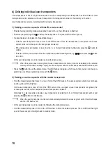
Page 18: ...he system does not recognise the user transponder and hence it cannot be deleted or the entered memory cell number is already empty the access system will emit 3 brief beeps and the LED will flash red Press the button to exit the delete mode The LED flashes red again which means that you can continue pro gramming or exit the programming mode with the button 2 Deleting a user transponder with the m...

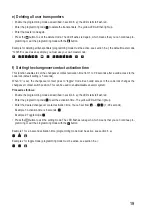
Page 19: ...er a valid access to the code lock default setting is 5 seconds When 0 is set the changeover contact goes to toggle mode Each valid access to the code lock changes the changeover contact switch position This can be used to enable disable an alarm system Proceed as follows Enable the programming mode as described in section 8 a the LED starts to flash red Enter the programming code to set the activ...

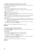
Page 20: ...in place regarding the duration of acoustic signals The acoustic signals generated by the access system are subject to country specific regulations even if they are not as loud as those of a siren or an alarm system Press the button to exit the setting mode The LED flashes red again which means that you can continue pro gramming or exit the programming mode with the button Example for a block for ...

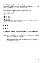
Page 21: ...ications programming mode must be active see section 8 a Example 2 for disabling beeps programming mode must be active see section 8 a j Resetting all settings to factory defaults pairing new master transponder The access system can be reprogrammed by resetting it to factory defaults The reset procedure also allows pairing of a master transponder if necessary You can use either the included master...

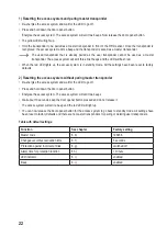
Page 22: ...y mode All the settings have been reset to factory defaults 2 Resetting the access system without paring master transponder De energise the access system and wait for the LED to go off Press and hold down the door opener button Energise the access system The access system will emit two beeps Wait about 10 seconds keep the door opener button pressed and do not release it The access system will emit...

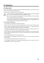
Page 23: ...sponder numbers Switch on the IR remote control by first removing the protective strip from the battery holder or inserting the battery Think of a master code consisting of 6 digits and programme it see section 8 b The default master code is 123456 the same applies after resetting the access system to factory defaults The included master transponder e g marked as Master Card is used only for quick...

Page 24: ...he toggle mode as described in section 8 f each valid user transponder permanently switches the changeover contact to the other position c Accessing via door opener button Briefly pressing the door opener button activates the changeover contact and the door opener for a preset time and the LED lights up green After enabling the toggle mode as described in section 8 f each press of the door opener ...

Page 25: ...reception LED is located right next to it The IR remote control must be held close enough to the access system approx 1 m for the latter to respond to it The front panel of the access system is exposed to direct sunlight or any other IR light source such as IR spotlight of a surveillance camera and its proper functioning is disturbed Hold the IR remote control closer to the access system The IR re...

Page 26: ...be paired via this card reader When the Wiegand controller uses a card reader for 125 kHz transponders pairing can be performed both via the access system and the external card reader Use an external card reader to check the functionality Changeover contact is permanently active and cannot be switched back The changeover contact activation time has been set to 0 and is in toggle mode Each valid ac...

Page 27: ...n The abbreviations for heavy metals in batteries are Cd Cadmium Hg Mercury Pb Lead name on rechargeable batteries e g below the trash icon on the left Used rechargeable batteries can be returned to collection points in your municipality our stores or wherever re chargeable batteries are sold You thus fulfil your statutory obligations and contribute to environmental protection Batteries rechargeab...

Page 28: ...eover contact relay Max contact rating 24 V DC 2 A Adjustable switching time 1 99 seconds or toggle mode default setting 5 seconds Wiegand connection yes output 26 bit protocol input 26 34 bit protocol with automatic recognition Transponder memory cells 2000 Mounting location indoors outdoors Protection class IP66 Ambient conditions Temperature 40 C to 60 C Cable length approx 25 cm Dimensions 115...

Page 29: ...29 ...

Page 30: ...30 ...

Page 31: ...31 ...

Page 32: ...ved Reproduction by any method e g photocopy microfilming or the capture in electronic data processing systems require the prior written approval by the editor Reprinting also in part is prohibited This publication represent the technical status at the time of printing Copyright 2021 by Conrad Electronic SE 2380477_V3_1021_02_VTP_m_en ...

Reviews: