background image


Page 8


3503.502.02 

Version 1.0 

7.  To  run  the  software,  use  the  shortcut  on  the  desktop  (created  by  the  installer)  or  run 

C:\OSV8\OSV7.exe. 


3.3 

Network card configuration 

In addition to above driver setting, you should specify the TCP/IP address: 


Press the windows button "Start", "Settings" then "Control panel". 


Double click on "Network Connections". 


Right click on the line corresponding to the network card on which  MYRIA camera is 
connected and choose "Properties". 


Highlight "Internet Protocol (TCP/IP)" then to click on the "Properties" button. 


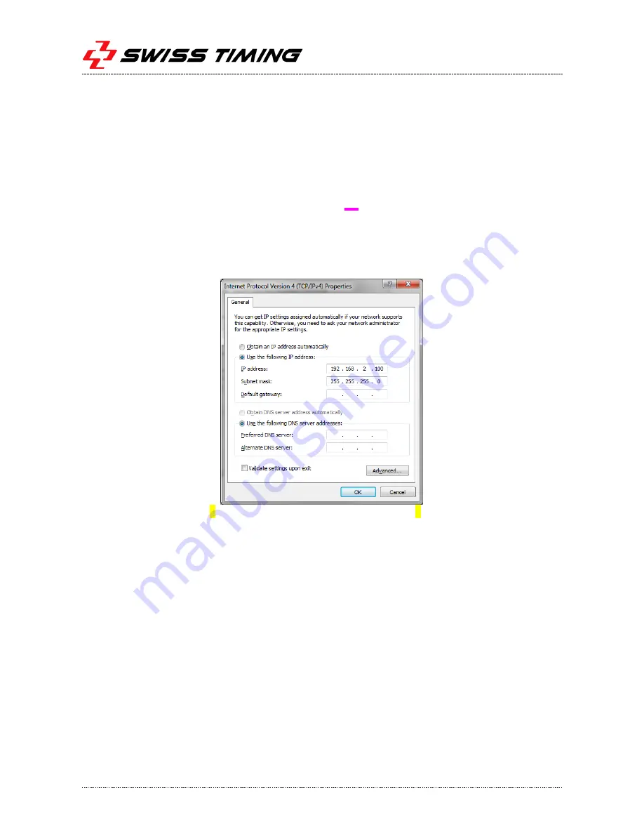
Click on "Use the following IP address:" and enter data, as in the picture below: 


Note: IP address is 192.168.2.100 for OSV MYRIA connection and 192.168.0.100 for OSV-STAR connection. 


Click  on  the  "OK"  button  of  this  window,  and  then  on  the  "OK"  button  of  the  previous 
Connection Properties” window. 

 
It  is  also  recommended  to  fix  the  transmission  speed  to  1Gb/s  between  the  computer  and  the 
camera (this setting is not available for all network interface): 


Press the windows button "Start", "Settings" then "Control panel". 


Double click on "System ". 


Click on the "Hardware" tab and then on the "Device Manager" button. 


Right click on the network adapter where the camera is connected and select "Properties". 

Summary of Contents for MYRIA 10

Page 1: ... 488 36 11 P O Box 138 Rue de l Envers 1 info swisstiming com CH 2606 Corgémont Switzerland www swisstiming com OMEGA Scan O Vision MYRIA PHOTO FINISH CAMERA USER S MANUAL 3503 502 02 l Version 1 0 l October 2017 MYRIA 10 MYRIA 16 ...

Page 2: ...ure to maintain a sufficient security distance from the public Documentation Updates Swiss Timing LTD reserves the right to make improvements in the products described in this documentation at any time without prior notice Furthermore Swiss Timing LTD reserves the right to revise this documentation in its content at any time and without any obligation to notify any person or organization of such r...

Page 3: ... 2 3 Power ON Power OFF 5 2 4 Indicators 5 3 SOFTWARE 6 3 1 Computer specification 6 3 2 Software installation 6 3 3 Network card configuration 8 3 4 Software use 9 3 4 1 Information about camera 9 3 4 2 Test Window 9 3 4 3 Synchronization Window 10 3 4 4 Camera settings 10 4 TECHNICAL SPECIFICATIONS 11 4 1 General specification 11 4 2 Electric specification 11 4 3 Certification 11 4 4 Connections...

Page 4: ......

Page 5: ...and its connections It also contains information to install the software and driver on your computer and specific software function for this camera The complete use of the software is described in the manual 3434 501 A 10x MYRIA 10 or 16x MYRIA 16 optical zoom lens is integrated in the camera housing It is fully remote controlled zoom iris and focus It allows setting the camera in almost any locat...

Page 6: ...iew 1 2 Definitions The camera is typically supplied with a support permitting the setting of its position according to 4 axes here are the definitions used in this manual Translation Horizontal displacement perpendicular to the finish line Pan Rotation in the horizontal plane Tilt Rotation in the vertical plane in the axis of the finish line Swivel Rotation in the vertical plane perpendicular to ...

Page 7: ... prevent the competitors in the foreground masking another Centre the tripod on the extension of the finish line If it is equipped with a spirit level align the bubble precisely in the middle of the reference mark Then slowly tighten all screws checking bubble does not move For a better stability spread the legs as far apart as possible and do not raise the central extension tube On the tripod fir...

Page 8: ... do manual recording of images it is recommended to connect a pushbutton option 2872 003 on the FINISH bananas Connect the 10m network cable Ethernet Gigabit 9051 1315 between the Ethernet connector on the camera and the PoE connector of the PoE injector power supply Connect the 2m network cable Ethernet Gigabit 9051 1317 between the LAN connector of the PoE injector and the computer Connect the p...

Page 9: ...escription Inclinometer left yellow If blinking see from rear the left side of the camera is too high The faster the LED blinks the closer the sensor is to vertical WiFi status blue ON WiFi enabled Ethernet status green Flashing when Ethernet activity General status green ON µC powered initialization in progress or freeze Fast blinking 5Hz µC working time based not sync Slow blinking 1Hz µC workin...

Page 10: ...work for computers connection 2nd network adapter different from camera 1Gb s recommended For example USB3 Ethernet adapter DeLock 62121 1Gb s recommended Various USB port for software installation USB port for software installation 3 2 Software installation 1 Install the software available on the delivered support Installer will also install PLEORA eBUS SDK 64 bit driver for camera Ethernet conne...

Page 11: ...rom the list of All Programs Pleora Technologies Inc eBUS SDK 4 Click on the Advenced button of GiGE VISION part 5 In the scroll list select the network adapter where the camera is connected Ensure that check boxes eBUS Universal Pro for Ethernet and Jumbo Packet are checked 6 Close the windows ...

Page 12: ... on the Properties button Click on Use the following IP address and enter data as in the picture below Note IP address is 192 168 2 100 for OSV MYRIA connection and 192 168 0 100 for OSV STAR connection Click on the OK button of this window and then on the OK button of the previous Connection Properties window It is also recommended to fix the transmission speed to 1Gb s between the computer and t...

Page 13: ...nd OSV MYRIA images with any OSV7 software configuration The complete use of the software is described in the manual 3434 501 available in the Documentation sub directory Following are some change related to MYRIA camera 3 4 1 Information about cameraWith Help About Hardware menu you can get a lot of information about the camera for example its inclination or the temperature inside the camera hott...

Page 14: ...of the three zoom square In Camera settings active the matrix view should be displayed Disable the horizontal references should be displayed Click on one of the three zoom at the right of the matrix view to select it Click in the matrix view to assign the center location of the vertical position horizontal position is automatically fixed Choice of timing line in matrix The vertical line timing lin...

Page 15: ...2m Zoom Aperture Focus MYRIA 16 16x 4 2o to 61 3o F1 8 1 0m Zoom Aperture Focus 4 2 Electric specification Condition Min Typ Max Unit Power supply PoE injector side up to 100m cable 48 56 V Power supply On camera input 42 56 V Power consumption 10m cable 14 15 W Power consumption 100m cable 19 21 W 4 3 Certification According to IEC 61326 1 2014 Class A equipment IEC 61000 4 2 2009 Electrostatic d...

Page 16: ...nal 1 TxRx A and VDC1 2 TxRx A and VDC1 3 TxRx B and VDC1 4 TxRx C and VDC2 5 TxRx C and VDC2 6 TxRx B and VDC1 7 TxRx D and VDC2 8 TxRx D and VDC2 I O Matching cable connector Binder serie 723 09 0129 70 12 Pin nbr Signal View A Not connected B Ready 1 C Finish 2 D Finish 2 E Start 2 F Start 2 G Rx RS232 input 3 H GND J 5VDC output max 100mA K PPS input L Ready 1 M Tx RS232 output 3 Notes 1 Outpu...

Page 17: ...is around 20 C 5 2 Maintenance Never touch the glass in the front of the camera with your fingers After use please always replace the protection cap It is recommended to clean the glass in the front of the camera regularly with a photographic link free cloth 6 APPENDICE 6 1 Index figures Figure 1 MYRIA front view 2 Figure 2 MYRIA bottom view 2 6 2 Version history Version Date Modifications since l...

Page 18: ......

Page 19: ...Swiss Timing LTD Phone 41 32 488 36 11 P O Box 138 Rue de l Envers 1 info swisstiming com CH 2606 Corgémont Switzerland www swisstiming com ...

Reviews: