background image


12 


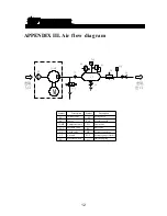
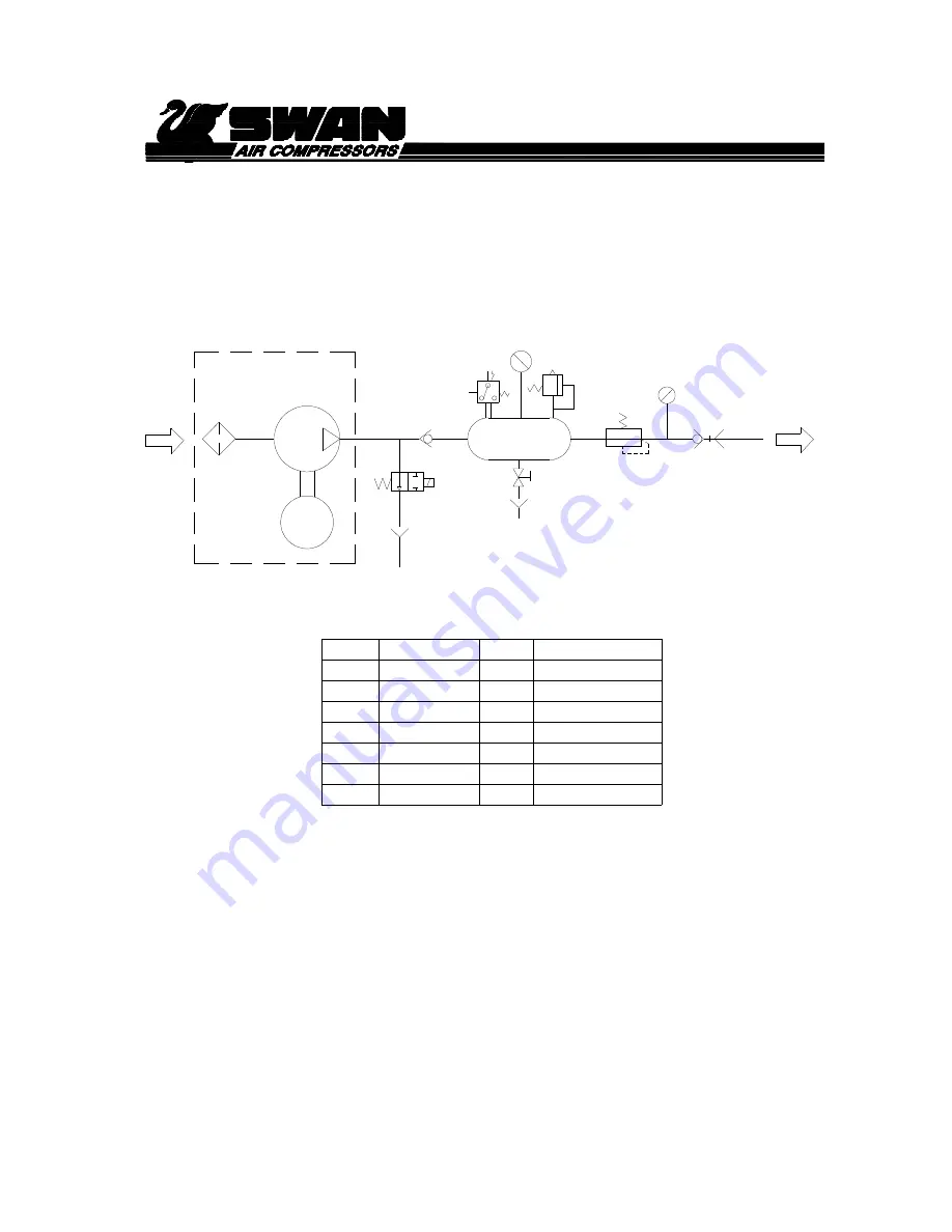
APPENDIX III. Air flow diagram 


Inlet air filter

SF

M

COMP

Compressor unit

SOL.

Solenoid valve

Motor

Description

Symbol

SV

PG.1

CV

Air tank

Check valve 

AT

PS

Ssfety valve

Pressure switch

DV

BV

PR

Description

PG.2

QC

Pressure regulator

Pressure gauge (Outlet)

Quick coupling 

M

空氣
入口

空氣

出口

SOL.

SF

COMP.

CV

AT

SV

PS

PG.1

DV

PG.2

QC

PR

Symbol

Pressure switch

Drain valve

Ball valve

Summary of Contents for DRS SERIES

Page 1: ...DRS SERIES OIL LESS AIR COMPRESSOR OPERATION MANUAL...

Page 2: ...h parts not manufactured by Tong Cheng serviced by unauthorized personnel or where recommended maintenance procedures have not been followed the warranty will be waived automatically This compressor i...

Page 3: ...escription function 4 III Installation and precautions 5 IV Operation 6 V Maintenance 6 VI Trouble shooting 8 APPENDIX I Air compressor configuration 10 APPENDIX II Electric circuit diagram 11 APPENDI...

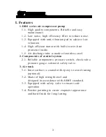
Page 4: ...tor inside 1 5 Air discharge tube is made of stainless steel 2 Components of control system 2 1 Reliable components pressure switch check valve pressure gauge solenoid safety valve 3 Air tank 3 1 Inne...

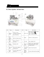
Page 5: ...2 Tank pressure gauge Indicate air tank pressure 3 Safety valve Tank over pressure protection 9 Air tank Store compressed air 4 Quick Coupling Discharge outlet 10 Electric cord plug Ensure correct vol...

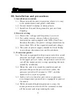
Page 6: ...supply should be fixed firmly to avoid any disconnection and break down 3 Protection points 3 1 The unit is equipped with pressure switch to avoid pressure too high when air tank pressure reaches to t...

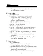
Page 7: ...r pressure rises normally 2 2 Check if loading current of motor remains in standard level 2 3 Check if all safety device work properly by hand 2 4 Never touch cover under operation Stay away from high...

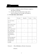
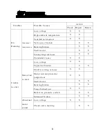
Page 8: ...month 300 hours 2 Periodically maintenance Item Weekly Monthly Yearly 2 Year Air tank drain valve Check and clean inlet air filter element Check and clean the ventilation area of the unit Check pressu...

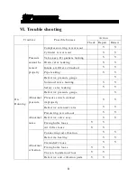
Page 9: ...V Defective pressure gauge V Solenoid valve leaking V V Safety valve leaking V V Abnormal pressure Defective pressure gauge V Pressure switch worked improperly V V Defective solenoid valve V V Abnorm...

Page 10: ...g broken V V Fault motor V V Connecting rod loose V V Crankshaft loose V V Unable to start Motor fail to start Low voltage V V Capacitor broken V V Electric wiring is loose V V Motor current protector...

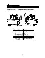
Page 11: ...iver Description NO NO 8 9 10 5 Drain valve assembly Check valve assembly 6 7 Pressure gauge Cable with plug Pressure switch 11 Hose 12 Solenoid valve 13 Anti vibration pads Description 1 13 4 14 8 9...

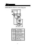
Page 12: ...11 APPENDIX II Electric circuit diagram Symbol Description P S SV Pressure switch Solenoid valve MC Compressor motor C Motor capacitor Over heat protector F PE Earth wire L1 L2 Electric cord...

Page 13: ...olenoid valve Motor Description Symbol SV PG 1 CV Air tank Check valve AT PS Ssfety valve Pressure switch DV BV PR Description PG 2 QC Pressure regulator Pressure gauge Outlet Quick coupling M SOL SF...

Page 14: ...TONG CHENG IRON WORKS CO LTD No 16 Ta Chin St Sec 2 Taichung Taiwan Tel 886 4 22612135 Fax 886 4 22628246 Web site www swanair com tw E mail swantc swanair com tw M01865H300E A...

Reviews: