background image

Page 90

N2000 Series User Manual

www.svsiav.com


Chapter 4. Decoder Options

IR Page

IR PAGE

Click the 

IR

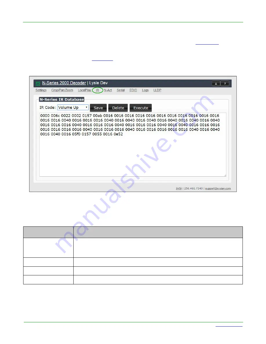
 link at the top of any of the main web pages to access the page shown in 

Figure 4-14

. This page 

allows you to upload and execute IR Pronto codes so that other vendor’s devices can be controlled through 
the Decoder’s IR connector. Commands can be saved for future use and executed later. The

 IR Code

 menu 

lists all saved IR commands. See 

Table 4-12

 for option descriptions.

Figure 4-14. IR Page

 Table 4-12. IR Page Options

Option

Description

IR Code

Create/select IR codes. Different vendors have different IR Pronto codes and can 
usually be found through a web search. Copy/paste new IR commands directly 
into the input space. 

Save

Save the current code.

Delete

Delete the current code.

Execute

Activate the selected code through the Decoder’s 

IR

 connector.

Summary of Contents for N2121

Page 1: ...800DOCN2000MNREV2 1 8 2015 User Manual Digital Media Distribution Switching Solution N2000 Series SVSi N Series Encoders Decoders N2121 N2211 N2221 N2141 2241 ...

Page 2: ...oders to the Network 23 Connecting Encoders to the Network and Configuring Stream Settings 25 Configuring Decoder and Encoder IP addresses if needed 29 How IP Address Changes Affect Unit Control 29 Changing IP Addresses 29 Option 1 Assigning IP Addresses Individually using the Settings page 29 Option 2 Assigning IP Addresses to Multiple Units using CSV files 30 Connecting Encoders to an Input Sour...

Page 3: ...Page 66 LLDP Page 67 Chapter 4 Decoder Options Decoder Introduction 68 Decoder Configuration Options 68 Settings Page 69 Decoder Setup Section 70 Advanced Settings 73 RS232 Settings 77 Network Setup Section 78 Status Section 80 Change Password 82 Software Section 83 EDID Section 84 Audio Downmixer Settings 85 Crop Pan Zoom Page 86 LocalPlay Page 88 IR Page 90 N Act Page 91 Serial Page 93 EDID Page...

Page 4: ...the Reader The contents of this manual are current as of the date of publication SVSi reserves the right to change the contents without prior notice In no event will SVSi be liable for any special incidental or consequential damages or for commercial losses even if SVSi has been advised thereof that result from issue or use of this publication Information in this document including URL and other I...

Page 5: ...Page 5 N2000 Series User Manual www svsiav com Conventions Notes provide additional useful information Cautions provide information that could prevent service interruption or damage to the equipment ...

Page 6: ...rovided documentation carefully before operating Follow all operating and other instructions carefully Do not use this product near heat sources such as radiators air ducts areas subject to direct intense sunlight or other products that produce heat Disclaimer While every effort has been made to ensure that the information contained in these instructions is accurate and complete no liability can b...

Page 7: ...y and if not installed and used in accordance with the instruction manual may cause harmful interference to radio communications Operation of this equipment in a residential area is likely to cause harmful interference in which case the users will be required to correct the interference at their own expense To comply with FCC and Industry Canada RF exposure limits this device must be installed to ...

Page 8: ...r supply and speeds installation Units can still be powered locally by 12VDC This allows easy rack mountable high density installations All units can be PoE powered except the N2211 Decoder Infrared IR emitter connection allows control of low cost IR only display devices Fast install with Phoenix connectors for power IR RS232 serial and analog audio interfaces Pass through DVI interface allows eas...

Page 9: ...orts one PoE The unit provides digital video output only REAR PANEL PORTS AND LEDS See Figure 1 1 Figure 1 2 and Figure 1 3 to identify the ports on the back of your Encoders and Decoders Figure 1 1 N2121 N2141 Encoder Rear Panel Figure 1 2 N2221 N2241 Decoder Rear Panel 9 1 12VDC Input not needed with PoE 2 Status Indicators 3 RJ45 Auto Sensing Gigabit Ethernet Switch Port PoE 4 RJ45 Auto Sensing...

Page 10: ...wire RJ45 female 10 100 1000 Mbps 10 100 1000Base T auto sensing gigabit Ethernet switch port Provides both the network connection and the power to the Encoders and Decoders Not available on the N2211 Decoder P1 8 wire RJ45 female 10 100 1000 Mbps 10 100 1000Base T auto sensing gigabit Ethernet switch port IR 2 pin terminal Phoenix connector Provides IR output only 33 to 60 kHz An emitter may be n...

Page 11: ...d input Dedicated audio output Not available on the N2211 Decoder DVI D OUTPUT DVI D female HDMI DVI digital video audio output Allows for video and embedded digital audio output DVI I INPUT DVI I female HDMI DVI digital video audio input Allows for the use of analog or digital video sources as well as embedded audio Applies to Encoders only Table 1 1 Rear Panel Descriptions Continued ...

Page 12: ...Page 12 N2000 Series User Manual www svsiav com Chapter 1 Introduction Application Examples APPLICATION EXAMPLES Figure 1 4 Loop Through DVI Port on Encoder Figure 1 5 IR and Serial Transmitter Port ...

Page 13: ...Page 13 N2000 Series User Manual www svsiav com Chapter 1 Introduction Application Examples Figure 1 6 Built In Scaling Through Encoders and Decoders Figure 1 7 Basic Networked AV ...

Page 14: ...Page 14 N2000 Series User Manual www svsiav com Chapter 1 Introduction Application Examples Figure 1 8 Multi Switch Enterprise Network ...

Page 15: ...nits If not using PoE connect either the P0 or P1 port to the network using an Ethernet cable Daisy chain configuration Once network connection is established to one unit you can daisy chain additional units by connecting Ethernet cables between devices using their P0 and or P1 ports Keep in mind that the number of units supported in this configuration is limited by bandwidth total aggregate strea...

Page 16: ...utput terminal block plug connector or Send audio embedded in the video connection to a monitor s speakers Note When the unit is not in use remove the power cable and disconnect any other cables e g Ethernet audio video connected to the Encoders and Decoders Note DVI D output is the digitally converted analog signal from the DVI I input An appropriate adapter or interface cable is required for DVI...

Page 17: ... steps 1 Remove the four screws from the bottom of the unit and use them to attach the mounting wings not included in shipment SVSi part number N9101 See Figure 2 1 2 Place the unit against the solid surface to which you want it mounted 3 Using standard hardware attach the unit through each of the slots of the newly attached mounting wings 4 Connect the appropriate cables necessary for your applic...

Page 18: ...The 12V power supply of the N9206 is the primary power source for the installed cards If the 12V power supply fails or is unplugged the cards will power down detect PoE if provided by switch and restart normally using PoE This usually results in a power loss of about one to two seconds The unit then reboots which takes another one to two minutes To rack mount N2000 Series cards into the N9206 Card...

Page 19: ...gure 2 4 Fully Populated Card Cage 6 For proper airflow cover any unused card slots with faceplate blanks Blanks are sold separately SVSi part number N9210 7 Make sure the Card Cage s power cord is plugged in for proper cooling Caution Keep the Card Cage s power cord plugged in at all times so that the internal fans are always running Not doing so could void the warranty of the cage and all instal...

Page 20: ...made for the addition of high speed video Our Networked AV solutions provide unsurpassed video and audio quality at bandwidths appropriate to any network segment or link Matrix switches as large as 1200x800 have been constructed on a house network using SVSi s equipment Alternatively many customers choose to deploy on physically separate networks in order to use low cost network appliances but kee...

Page 21: ...000 devices are shipped in Auto IP mode with a default IP address of 169 254 xxx xxx Before beginning installation you will need to make some changes to the computer running N Able These steps show how this can be accomplished in a Microsoft Windows environment 1 From the Start menu select Control Panel Network and Sharing Center 2 Select Change adapter settings 3 Double click the wired interface ...

Page 22: ...to configure the existing network SVSi units will not self assign in the 169 254 0 xxx range Note If the computer has a statically assigned IP address click the Advanced button Then click Add to enter a unique 169 254 xxx xxx address with a subnet of 255 255 0 0 4 Scroll down in the list to the Internet Protocol Version 4 TCP IPv4 option Highlight it and click the Properties button 5 Enable the Us...

Page 23: ...etwork and power connection In non PoE applications connect a 12V regulated power supply N9312 to the two pin terminal block plug connector labeled 12V 2A 2 Connect the display you would like to use for that Decoder monitor projector etc to the Decoder s DVI D Output port using a DVI cable or HDMI through adapter This must be a digital video connection Figure 2 5 Decoder Connections 3 Repeat Steps...

Page 24: ... Manual www svsiav com Chapter 2 Installation Step by Step Installation Instructions Caution Do not run wiring that is connected to a PoE PSE port outside of the building where the PSE resides It is for intra building use only ...

Page 25: ...opulated itself with the installed units See Figure 2 6 Figure 2 6 Unit Management Page 3 Find your Encoder in the list N2000 units are displayed on the following tabs Unit Management tab N2000 units have N2000 Encoder Decoder listed in their Type fields Video Matrix tab N2000 units are found on the N2000 sub tab as shown in Figure 2 7 Note In order for the unit to receive PoE it must be connected...

Page 26: ...gure 2 7 Video Matrix Page Encoders are listed across the top of the page Decoders are listed down the left side of the page Red Text No video source encoder or no display decoder Gray Text Video output for this unit is disabled Black Text Unit is in live play mode Blue Text Unit is playing locally stored content ...

Page 27: ... in for the first time These can be changed later on the Settings page Default username admin Default password password Figure 2 8 Login Page 5 The Settings page is displayed see Figure 2 9 6 Change the Stream setting We recommend setting Stream to a number between 2 and 254 it is required that the number be less than 32 512 The Login page is only displayed if N Able s stored username password doe...

Page 28: ...at these steps until all Encoders are connected to the network and configured with an appropriate Stream number Note Each Encoder s Stream number must be unique to all other Encoders on the network Note Screen by screen descriptions of the web interface options are provided for your reference in Chapter 3 Encoder Options and Chapter 4 Decoder Options ...

Page 29: ...the first IP address to be in the range of the default N Series IP settings i e in the 169 254 xxx xxx range AND Configure a second IP address in the range of the IP address you are planning to assign to the units or when using DHCP an address within the defined range for your network Changing IP Addresses There are two ways to assign new IP addresses to your N2000 units using N Able Option 1 Log ...

Page 30: ... as scan the network for new devices regardless of IP configuration To configure units using a CSV file follow these steps 1 Make sure that you have performed an Auto Discover on the Unit Management tab of N Able since connecting all of the new units to the network 2 From N Able s main menu bar select N Able Export CSV 3 Click Yes on the pop up box informing you that a CSV file is about to be gene...

Page 31: ... This connection from an Encoder DVI I port female to an input source is accomplished using either a DVI I cable or HDMI through adapter 1 Connect the source you would like to use for the Encoder camera laptop etc to the Encoder s DVI I Input port using a DVI I cable or HDMI through adapter This connection can be digital or analog 2 Repeat until all Encoders are connected to their sources Figure 2...

Page 32: ...d or audio being transmitted out to the display device Seamless Switching The N2000 Series supports seamless switching capability if the scalers in the Encoders are all set to the same resolution and refresh rate If the scalers are off all of the sources must have the same resolution and refresh rate To get streams onto a Decoder use the Video Matrix tab to route video from an Encoder to a Decoder...

Page 33: ...control assign fixed IP addresses for each SVSi component adjust variable bit rate for each video stream etc Visit our website and refer to Table 2 2 on page 35 for more details on the available N Command Controllers Third Party Controllers The N2000 Series is capable of interfacing with third party control systems such as Savant Utelogy AMX Altinex or Crestron SVSi can provide Crestron modules wh...

Page 34: ...er 2 Installation Other Control Options Software Bundles Included With N Command Panel Builder Build attractive touch panels to control the N2000 and third party equipment Wall Builder Design walls of any size in minutes using SVSi s Encoders and Decoders ...

Page 35: ...Page 35 N2000 Series User Manual www svsiav com Chapter 2 Installation Other Control Options Table 2 2 Management Options for the N2000 Series ...

Page 36: ...eb interface you can access all other main pages by clicking the links in the top navigation bar Figure 3 1 shows the main navigation bar and provides hot links to the sections of this chapter which describe them Figure 3 1 Section Links Settings Page on page 37 Crop Pan Zoom Page on page 56 HostPlay Page on page 58 IR Page on page 60 N Act Page on page 61 Serial Page on page 63 EDID Page on page ...

Page 37: ...veral sections and also has links to other dialog boxes for additional configuration options Refer to the following sections for detailed descriptions Encoder Setup Section on page 38 Advanced Settings on page 42 RS232 Settings on page 46 Network Setup Section on page 47 Status Section on page 49 Change Password on page 51 Software Section on page 52 EDID Section on page 53 DVI Pass Thru Settings ...

Page 38: ...anual www svsiav com Chapter 3 Encoder Options Encoder Setup Section Encoder Setup Section The Encoder Setup section of the Settings page is shown in Figure 3 3 Options are described in Table 3 1 Figure 3 3 Encoder Setup Section ...

Page 39: ...t transmit stream number To better understand this setting think of Encoders more like a channel on a cable box rather than a traditional AV Matrix Each Encoder must have a unique stream number just like every channel must have a unique channel number e g Food Network and HGTV cannot both be on channel 201 Audio Input Type Select Unbalanced single ended or Balanced analog audio input Scaler Enable...

Page 40: ...le to stop the transmission of audio data onto the network Audio Source Set the audio source to be disabled enabled or selected automatically see note The AUTO setting always corresponds to HDMI audio as long as there is an HDMI source If the source is unplugged it will automatically fall back to analog audio if there is an analog source plugged in Color Space Correction Set the color space settin...

Page 41: ...ou are connecting a non SVSi device to a port for network based control Disable P1 Completely disables the P1 port for all traffic Once disabled anything connected to the P1 port will no longer be available on the network Cancel Click to return all controls to the last saved configuration Save Click to accept changes made to these controls Table 3 1 Settings Page Encoder Setup Section Continued Op...

Page 42: ...iav com Chapter 3 Encoder Options Advanced Settings Advanced Settings The section of the Settings page shown in Figure 3 4 is displayed when you click the Advanced Settings link Options are described in Table 3 2 Figure 3 4 Advanced Settings ...

Page 43: ...gnal Does not affect digital audio Audio Gain Right Slide right to provide a POST ENCODE boost in the right channel s audio signal This can help compensate when the source is providing a weak audio signal Does not affect digital audio Brightness Use sliders to raise or lower RGB values of the Encoder POST ENCODE Only affects analog video Does not affect digital video Horz Offset Enter the number o...

Page 44: ...tify units This is useful for larger network integrations when broadcast packets will not cover the entire network Enabled by default Discovery Interval secs Determine how often in seconds the unit transmits discovery packets TTL Select the Time To Live TTL for the transmit audio and video streams Limits the lifespan of data on the transmit audio and video streams to improve performance VLAN Taggi...

Page 45: ...ion purposes IR Repeat Holdoff Set the repeat delay between IR commands The default setting is 90 ms This is the amount of time before a new command is sent For example when pressing and holding the volume button on a remote control this is how long until the command is repeated Maintain Aspect Ratio When scalers are enabled enabling this check box maintains the source s aspect ratio Enable SNMP E...

Page 46: ...Settings Table 3 3 Settings Page RS232 Settings Option Description RS232 Baud Rate Select the appropriate baud rate for the RS232 serial interface Default is 9600 RS232 Data Bits Select the appropriate data bit count for the RS232 serial interface Default is 8 RS232 Parity Select the appropriate parity for the RS232 serial interface Default is no parity none RS232 Stop Bits Select the appropriate ...

Page 47: ... DHCP an IP Address in the range of the DHCP server on the network will be automatically assigned to the N2000 Encoder When set to STATIC an IP address Netmask and Gateway address must be manually entered Using DHCP is generally not recommended If the device is set to DHCP and fails to receive an address from the DHCP server in time it will revert back to the AUTO IP Address 169 254 xxx xxx until ...

Page 48: ...ns Network Setup Section Trial Save Click to initially save IP address changes Once you log in to the unit using the new address you will be able to confirm and accept the changes permanently Table 3 4 Settings Page Network Setup Section Continued Option Description Notes ...

Page 49: ...urce DVI Status Pass Thru Indicates if a display device is connected to the Encoder Current Bandwidth This is a snapshot of the unit as properties were loaded to the browser not a live counter Refresh the page to get an updated bandwidth Port 50001 Source IP Shows the IP address of the currently connected device or displays Disconnected if no connection exists Port 50001 can only accept a single e...

Page 50: ...rejected However connection attempts from the same IP will override the current connection Serial Source IP Shows the IP address of the currently connected device or displays Disconnected if no connection exists Only a single external connection can be accepted on the port If a device is currently showing the port occupied by a control system or other device then other connections will be rejected...

Page 51: ...2000 Encoder interface password enter the current password in the field labeled Old Password and enter a new password in the New Password and Confirm Password fields Click Change PW to accept the new password Figure 3 8 Change Password This password needs to match N Able s stored password to allow auto login using N Able ...

Page 52: ...000 Encoder MAC Address Displays the MAC address of the network interface of the N2000 Encoder Firmware Version Displays the date code for the currently running version of the N2000 Encoder internal firmware Web Version Displays the date code for the currently running version of the web interface Factory Restore Click to restore the device to the original factory settings This resets everything ex...

Page 53: ...from the options available Then click Reset EDID This will work for most sources and is most often set to Stereo 2 channel Option 2 When using an EDID captured from a source connected to an Encoder paste the data in to the white EDID block overwriting existing EDID Then click Set EDID Figure 3 10 EDID Section The source will need to be disconnected while modifying EDID settings Table 3 7 Settings ...

Page 54: ... Options EDID Section Set EDID Pass thru Set if you want to copy the current EDID to the Encoder s pass thru port Reset EDID Choose a standard EDID from the drop down menu and click Reset EDID to apply Table 3 7 Settings Page EDID Section Continued Option Description ...

Page 55: ...tput audio over the HDMI connection Selecting Auto bases audio output on the settings of the connected source device YCbCr 4 2 2 Output For color conversion Can force to RGB on set output based on connected device s reported settings Default and preferred setting is Off Simplified DVI Detect When enabled detects DVI solely based on the hot plug detection Enable to help prevent displays monitors fr...

Page 56: ...t the top of any of the main web pages to access the page shown in Figure 3 12 This page allows you to customize the viewable portion of the input See Table 3 9 for option descriptions Figure 3 12 Crop Pan Zoom Page Note The Scaler check box must be enabled for changes on this page to take effect See Table 3 1 on page 39 for more information ...

Page 57: ...ea bottom right 16 9 Aspect Ratio Enable to force to a 16 9 ratio No Crop Click to disable existing crop settings and return unit to default output settings Execute Crop Reference Click to execute changes Save Crop Reference Click to save the current settings and store them as a preset for later use Presets can be used by third party controllers Stored Crop Presets Use this section of the page to ...

Page 58: ...ss the page shown in Figure 3 13 This page allows you to upload new images to the Encoders and configure the image playlists The playlist will be shown on the display when no video is being transmitted or received You can show a single image or set up multiple images to be displayed at a customized animation rate See Table 3 10 for option descriptions Figure 3 13 HostPlay Page ...

Page 59: ...HostPlay output resolution The playlists that were uploaded in that resolution are then displayed for your selection Audio Choose an audio file to play while the HostPlay image is on the screen Image list Allows you to customize what images are displayed the transition time for each image etc Image Audio DB This section provides the ability to upload image and audio files to the N2000 Encoder data...

Page 60: ...nnector Commands can be saved for future use and executed later The IR Code menu lists all saved IR commands See Table 3 11 for option descriptions Figure 3 14 IR Page Table 3 11 IR Page Options Option Description IR Code Create select IR codes Different vendors have different IR Pronto codes and can usually be found through a web search Copy paste new IR commands directly into the input space Sav...

Page 61: ...n when the Encoder powers up You can add multiple commands for each event See Table 3 12 for option descriptions Figure 3 15 N Act Page Table 3 12 N Act Page Options Option Description Enable Events Enable to activate the configured events Power on Event Create delete test events to be performed when the Encoder powers on Visit our website for more details on Application Programming Interface API ...

Page 62: ...when the Encoder is disconnected from a video source The Trigger Delay field specifies how long the device has to be disconnected for the command to be executed This keeps accidental momentary disconnects from triggering the command sequence Save Events Click to save changes made to this page Table 3 12 N Act Page Options Continued Option Description ...

Page 63: ...ws you to upload and execute commands used for direct control of serial devices Commands may be saved for future use and executed later The Serial Code menu lists all saved commands See Table 3 13 for option descriptions Figure 3 16 Serial Page If the Port 5004 Serial Port is currently in use by another device sending commands from the Serial page will always return a No Data message and fail to s...

Page 64: ...that can usually be found through a web search Copy paste new commands in either ASCII or HEX directly into the appropriate input space Save Save the current code Delete Delete the current code Execute Apply the selected code to the Encoder s serial connection ASCII and HEX Paste serial commands directly into either the ASCII or HEX field Response View responses provided by the device receiving th...

Page 65: ...formation that it communicates to the output device This page allows you to view that information See Table 3 14 for option descriptions Figure 3 17 EDID Page Table 3 14 EDID Page Options Option Description Pass thru Displays EDID information for the display connected to the Encoder s pass thru port Local Displays EDID information for the Encoder This information is being provided to the source co...

Page 66: ... the Logs link at the top of any of the main web pages to access the page shown in Figure 3 18 The Logs page displays a command log that lists all TCP and UDP messages the unit receives It also displays the web browser s IP address and gives you options to Refresh and Reset Logs Figure 3 18 Logs Page ...

Page 67: ...LDP PAGE Click the LLDP link at the top of any of the main web pages to access the page shown in Figure 3 19 The LLDP page displays information from the Link Layer Discover Protocol LLDP packet which identifies the port number and switch the device is connected to Figure 3 19 LLDP Page ...

Page 68: ...you can access the GUI main pages by clicking the links in the top navigation bar Figure 4 1 shows the main navigation bar for the Decoder and provides hot links to the sections of this chapter which describe them Figure 4 1 Section Links Settings Page on page 69 Crop Pan Zoom Page on page 86 LocalPlay Page on page 88 IR Page on page 90 N Act Page on page 91 Serial Page on page 93 EDID Page on pag...

Page 69: ...eral sections and also has links to other dialog boxes for additional configuration options Refer to the following sections for detailed descriptions Decoder Setup Section on page 70 Advanced Settings on page 73 RS232 Settings on page 77 Network Setup Section on page 78 Status Section on page 80 Change Password on page 82 Software Section on page 83 EDID Section on page 84 Audio Downmixer Settings...

Page 70: ...Table 4 1 Settings Page Decoder Setup Section Option Description Notes Device Name Enter a user friendly name for the unit More descriptive names in this field help you organize and manage the SVSi system efficiently Names based on the unit s location and function are very useful Some good examples are Lobby Left VGA for left side of lobby VGA input or CR201 HDMI for Conference Room 201 HDMI input...

Page 71: ...CD the Scaler check box must be enabled for this to be applicable Live Local Select live video or locally stored images for transmission to the video output device e g LCD When video is not available it automatically goes into local mode When video is not available the most recently played local playlist is displayed Mute Enable to mute output audio Lineout Volume This slider controls the output g...

Page 72: ...ou are connecting a non SVSi device to a port for network based control Disable P1 Completely disables the P1 port for all traffic Once disabled anything connected to the P1 port will no longer be available on the network Cancel Click to return all controls to the last saved configuration Save Click to accept changes made to these controls Table 4 1 Settings Page Decoder Setup Section Continued Op...

Page 73: ...iav com Chapter 4 Decoder Options Advanced Settings Advanced Settings The section of the Settings page shown in Figure 4 4 is displayed when you click the Advanced Settings link Options are described in Table 4 2 Figure 4 4 Advanced Settings ...

Page 74: ...continue playing the last valid video frame if the network connection is lost When enabled Local Play will not appear Gen 1 Compatibility Set compatibility with the color space of legacy equipment to be disabled enabled or selected automatically based on the identifying information in the video stream DVI off on stream loss Select to disable the video output drive when the video stream is not avai...

Page 75: ...lt setting is 25 ms IR commands are sent in two parts This setting is the time in milliseconds between transmission of part one and part two The second part of the command is inverted for confirmation purposes IR Repeat Holdoff Set the repeat delay between IR commands The default setting is 90 ms This is the amount of time before a new command is sent For example when pressing and holding the volu...

Page 76: ...ettings Maintain Aspect Ratio When scalers are enabled enabling this check box maintains the source s aspect ratio Enable SNMP Enable to allow the device to send Simple Network Management Protocol SNMP packets Table 4 2 Settings Page Advanced Settings Continued Option Description Notes ...

Page 77: ...Settings Table 4 3 Settings Page RS232 Settings Option Description RS232 Baud Rate Select the appropriate baud rate for the RS232 serial interface Default is 9600 RS232 Data Bits Select the appropriate data bit count for the RS232 serial interface Default is 8 RS232 Parity Select the appropriate parity for the RS232 serial interface Default is no parity none RS232 Stop Bits Select the appropriate ...

Page 78: ...y assigned to the N2000 Decoder by the control software When set to DHCP an IP Address in the range of the DHCP server on the network will be automatically assigned to the N2000 Decoder When set to STATIC an IP address Netmask and Gateway address must be manually entered Using DHCP is generally not recommended If the device is set to DHCP and fails to receive an address from the DHCP server in tim...

Page 79: ...ddress of the N2000 Decoder When in STATIC mode enter a new Gateway address into this field Trial Save Click to initially save IP address changes Once you log in to the unit using the new address you will be able to confirm and accept the changes permanently Table 4 4 Settings Page Network Setup Section Continued Option Description Notes ...

Page 80: ...ys Disconnected if no connection exists Port 50001 can only accept a single external connection at a time If a device is currently showing the port occupied by a control system or other device then other connections will be rejected However connection attempts from the same IP will override the current connection Port 50002 Source IP Shows the IP address of the currently connected device or displa...

Page 81: ...tion exists Only a single external connection can be accepted on the port If a device is currently showing the port occupied by a control system or other device then other connections will be rejected However connection attempts from the same IP will override the current connection Flush buttons These buttons reset the port Table 4 5 Settings Page Status Section Continued Option Description Notes ...

Page 82: ...2000 Decoder interface password enter the current password in the field labeled Old Password and enter a new password in the New Password and Confirm Password fields Click Change PW to accept the new password Figure 4 8 Change Password This password needs to match N Able s stored password to allow auto login using N Able ...

Page 83: ...000 Decoder MAC Address Displays the MAC address of the network interface of the N2000 Decoder Web Version Displays the date code for the currently running version of the web interface Firmware Version Displays the date code for the currently running version of the N2000 Decoder internal firmware Factory Restore Click to restore the device to the original factory settings This resets everything ex...

Page 84: ...apter 4 Decoder Options EDID Section EDID Section The section of the Settings page shown in Figure 4 10 is displayed when you click the Show EDID link This section displays the EDID of the output device connected to the Decoder Figure 4 10 EDID Section ...

Page 85: ... when receiving a 7 1 audio source Center Gain slider Set percentage of audio on center channel mixed into left and right output when downmixing Front Gain slider Set percentage of audio on front left and right channels mixed into left and right output respectively Surround Gain slider Set percentage of audio on surround when downmixing left and right channels mixed into left and right output resp...

Page 86: ...the viewable portion of the input See Table 4 9 for option descriptions Figure 4 12 Crop Pan Zoom Page Table 4 9 Crop Pan Zoom Page Options Option Description X1 Y1 Set pixel coordinates of viewing area top left X2 Y2 Set pixel coordinates of viewing area bottom right 16 9 Aspect Ratio Enable to force to a 16 9 ratio No Crop Click to disable existing crop settings and return unit to default output...

Page 87: ...Crop Reference Click to save the current settings and store them as a preset for later use Presets can be used by third party controllers Stored Crop Presets Use this section of the page to select delete export import cropping presets Table 4 9 Crop Pan Zoom Page Options Continued Option Description ...

Page 88: ... the screen shown in Figure 4 13 This page allows you to upload new images to the Decoders and configure the image playlists The playlist will be shown on the display when no video is being transmitted or received You can show a single image or set up multiple images to be displayed at a customized animation rate See Table 4 11 for option descriptions Figure 4 13 LocalPlay Page ...

Page 89: ...it playlist names Output Mode Select the resolution you want the image s to play in Audio Select an audio file to play while the LocalPlay image is on the screen Image List Allows you to customize what images are displayed the transition time for each image etc Image Audio DB This section allows you to upload images to the N2000 Decoder image database You can also use the Fill field to customize t...

Page 90: ...nnector Commands can be saved for future use and executed later The IR Code menu lists all saved IR commands See Table 4 12 for option descriptions Figure 4 14 IR Page Table 4 12 IR Page Options Option Description IR Code Create select IR codes Different vendors have different IR Pronto codes and can usually be found through a web search Copy paste new IR commands directly into the input space Sav...

Page 91: ...nnection without the use of an outside controller For example you can tell a projector and lights to come on when the Decoder powers up You can add multiple commands for each event See Table 4 13 for option descriptions Figure 4 15 N Act Page Table 4 13 N Act Page Options Option Description Enable Events Enable to activate the configured events Power on Event Create delete test events to be perfor...

Page 92: ... connected for the command to be executed DVI Disconnected Event Create delete test events to be performed when the Decoder is disconnected from the output display The Trigger Delay field specifies how long the device has to be disconnected for the command to be executed This keeps accidental momentary disconnects from triggering the command sequence Save Events Click to save changes made to this ...

Page 93: ...ws you to upload and execute commands used for direct control of serial devices Commands may be saved for future use and executed later The Serial Code menu lists all saved commands See Table 4 14 for option descriptions Figure 4 16 Serial Page If the Port 5004 Serial Port is currently in use by another device sending commands from the Serial page will always return a No Data message and fail to s...

Page 94: ...that can usually be found through a web search Copy paste new commands in either ASCII or HEX directly into the appropriate input space Save Save the current code Delete Delete the current code Execute Send the selected code out the Decoder s serial connection ASCII and HEX Paste serial commands directly into either the ASCII or HEX field Response View responses provided by the device receiving th...

Page 95: ...D PAGE Click the EDID link at the top of any of the main web pages to access the page shown in Figure 4 17 Every display has stored information that it communicates to the output device This page allows you to view the EDID information of the connected output display Figure 4 17 EDID Page ...

Page 96: ...ick the Logs link at the top of any of the main web pages to access the page shown in Figure 4 18 The Logs page displays a command log that lists all TCP and UDP messages the unit receives It also displays the unit s IP address and gives you options to Refresh and Reset Logs Figure 4 18 Logs Page ...

Page 97: ...LDP PAGE Click the LLDP link at the top of any of the main web pages to access the page shown in Figure 4 19 The LLDP page displays information from the Link Layer Discover Protocol LLDP packet which identifies the port number and switch the device is connected to Figure 4 19 LLDP Page ...

Page 98: ... instead of the video from the source Verify Encoder is in LivePlay mode its name will display in black text on the Video Matrix page You can change to Live mode on the Settings page see Table 3 1 on page 39 for more details Verify source is attached and is outputting a valid signal DVI LED on Encoder is on Unsupported Resolution graphic displays Change source resolution to a valid resolution try ...

Page 99: ...rough the Encoder Make sure that analog converter is in a DVI I pin out Note All SVSi outputs are digital only DVI pass thru on Encoder and DVI output on Decoder OR If using a Y cable N9420 and an HDMI source is already connected to the Encoder disconnect the HDMI source Encoders give preference to HDMI and will not allow analog signal to pass while it is connected Video output is stuttering This ...

Reviews: