Chapter 2: Installation
2-31
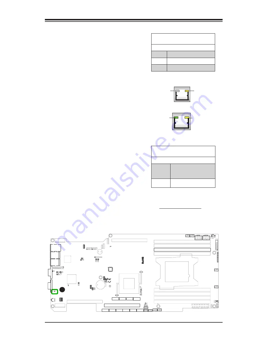
LAN Port LEDs
The LAN ports are located on the I/O
backpanel of the motherboard. Each
Ethernet LAN port has two LEDs.
The yellow LED indicates activity,
while the Link LED may be green,
amber, or off to indicate the speed of
the connections. On the IPMI port,
the yellow LED on the right indicates
activity, while the green LED on the
left indicates the speed of the con-
nection. See the table at right for
more information. See the tables at
right for more information.
2-8 Onboard Indicators
LAN
Link LEDs (Green/Amber/Off)
LED Color Definition
Off
No Connection or 10 Mbps
Green
100 Mbps
Amber
1 Gbps
Activity LED
Link LED
LAN
LAN 1/LAN 2
IPMI LAN
(X8ST3-F)
Link LED
Activity LED
IPMI LAN
Standby PWR LED (LED2)
LED Status
Status Definition
Off
System unplugged or
power supply is switched
off
On
Standby Power On
Standby Power (LED2)
The Standby Power LED is located
at LED2 on the motherboard. When
LED2 is on, it means that the AC
power cable is connected and the
power supply hard switch is on, indi-
cating that power is flowing through
the power supply and into the moth-
erboard. The system may or may not
be running.
JI2C1
1
JPW
1
1
11
10
20
JUIDB1
1
2
JPW2
5
8
4
1
JPW3
5
8
4
1
JLAN
2
JLAN
1
JSD1
1
3
J1
3
JPCIE3
JPCIE1
JPCIE2
12
7
8
1
2
7
8
2
8
JST
BY
1
3
1
JIPM
B1
X9SRG
RE
V:
1.00
DESIGNED IN USA
MH
5
JD1
7
SATA6
1
7
SATA5
1
7
SATA4
7
1
SATA3
7
1
JF
1
20
19
2
1
SAS3
7
1
SAS1
1
7
SAS2
7
1
SATA2
1
7
SATA1
7
1
SAS4
7
1
A
J17
SP
1
+
JBT1
LED2
A
C
LE2
C
A
LE1
A
C
BD1
AC
BT
1
JOH1
J28
1
JL1
1
C509
JVGA
1
JTPM1
1
2
19
20
J26
1
2
7
J2
3
1
2
7
JCOM1
FAND
1
FANC
4
1
FANB
4
1
FANA
4
1
FAN4
1
4
FA
N1
1
FA
N3
4
1
FA
N2
4
1
J6
J5
J12
J7
J4
J2
J3
J1
JI2C3
3
1
JI2C2
1
3
JPL1
1
3
JPL2
1
3
JW
D
JP
ME1
3
1
JPB1
3
JPG1
3
1
JPR1:
1-2:NORMAL
2-3:BIOS RE
CO
VE
RY
1-2:NORMA
L
2-3:ME RE
CO
VE
RY
SLOT3 PCIE 3.0X8
SXB2
B
SXB2
A
SXB1A
US
B
JBT1:CMOS CLEAR
JSD1: PWRSDO
M
PW
R
JF
1
ON
FA
IL
RS
TP
S
2
NIC
1
NIC
LED
UI
D
LED
LED
PW
R
HD
DX
NM
I
DIMMA1
2-3:NM
I
1-2:RST(DE
FA
UL
T)
JWD:
WA
TC
H DOG
TIMER
LAN
1
LAN2
UI
D
JI2C2/JI2C3 1-2:Enable 2-3:Disabl
e
WRITE PR
OT
EC
T
JWP1
:
JOH1:OVER HEA
T LED
US
B
SXB1B
1-2:RST 2-3:NIM
I
JWD:
2-3:DISABLE
1-2:ENABLE
JPL2:LAN
2
2-3:DISABLE
1-2:ENABLE
JPL1:LAN
1
JP
MB
:CHASSIS INTRUSION
JL1
I-SATA4
I-SATA2
DIMMC1
I-SATA3
I-SATA0
VG
A
I-SATA5
I-SATA1
COM1
USB/0/1
JD1:
4-7:SPEAKER
1-2:PWR_LED
OF
F:
Disabl
e
JP
ME1:
JI2C1
ON:Enabl
e
2-3:DISABLE
1-2:ENABLE
JPB1: BMC
2-3:Disabl
e
1-2:Enable
JPG1:
VG
A
CPU
JTPM1: TPM/PORT80
JST
BY
1:ST
AND
BY
POWER FOR DO
M
A
A. Standby Power LED
Summary of Contents for X9SRG-F
Page 1: ...USER S MANUAL Revision 1 0a X9SRG F...
Page 26: ...1 14 X9SRG F Motherboard User s Manual Notes...
Page 60: ...2 34 X9SRG F Motherboard User s Manual Notes...
Page 68: ...3 8 X9SRG F Motherboard User s Manual Notes...
Page 96: ...4 28 X9SRG F Motherboard User s Manual Notes...
Page 98: ...A 2 X9SRG F Motherboard User s Manual Notes...


