Supero SuperWorkstation 5037A-i2-MA015 User Manual Download Page 14

2-2

S

uper

W

orkstation 5037A-i2-MA015 User's Manual
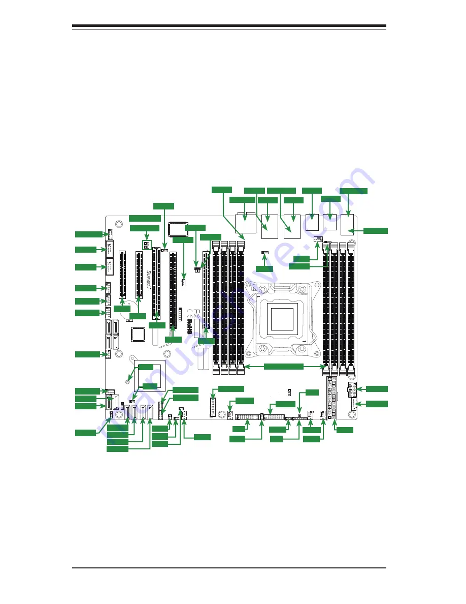
Figure 2-1. Layout

2-3 Motherboard 

Layout

This section provides details on the motherboard and jumper settings that may be 

useful when setting up the system.

T-

SGPIO1

3-SGPIO1

3-SGPIO2

T-

SGPIO2

I-SA
TA5

I-SA
TA4

I-SA
TA3

I-SA
TA2

I-SA
TA1

I-SA
TA0

JPTM1

SAS0

SAS1

SAS2

SAS3

JUSB1617

9

2

1

JFPAUDIO

JSTBY

1

3

B81

B82

A81

A82

PCIE4

JPCI3

JWF1

1

3

JC

OM2

1

5

6

JC

OM1

JUSB89

JUSB1011

1

7

JUSB1213

1

CPU1

JUSB45

JUSB23

JKBMS_USB01

JAUDIO1

JLAN2_USB67

BT1

+

PCIE1

PCIE2

DIMM2A

DIMM3A

DIMM4A

DIMM1B

DIMM2B

DIMM3B

DIMM4B

DIMM1A

JF1

JD1

JTAG1

6

1

RE

V:1.01

Te

st

ed t

o

 C

o

mply

W

ith FC

C Standar

d

s

FOR HOME OR OFFICE USE

DESIGNED IN USA

MAC

SAS C

ODE

BAR C

ODE

JPW2

PCIE6

1

JPI2C1

JB

T1

JPW1

1

JSPDIF_OUT

1

JSPDIF_IN

JI2C2

1

JI2C1

1

1

JL1

1

JCF1

1

JOH1

DP2

3

1

JP

ME1

JPAC1

JWD1

JVR2

JPL2

JPUSB1

JP

ME_DBG

4

FANA

FAN3

FAN1

FAN2

FAN4

MH3

MH7

MH4

MH8

MH1

MH9

MH6

MH5

H*

Pin1:RAID_KEY_PCH

JRK1

Pin2:Ground
Pin3:PCH_DYN_SKU

:TPM/PRO80

OFF

:By BIOS

JFP
A

UDIO_EN1

ON:F

or

ce

 Enable

USB3.0 2/3

2-3:Normal

1-2:BIOS recovery

JPBIOS1

JPME_DBG
1-2:ME Debug
2-3:Normal
JPME1
1-2:ME recovery
2-3:Normal

SL

O

T6 PCI-E 3.0 X16

SL

O

T4 PCI-E 3.0 X16

SL

O

T2 PCI-E 3.0 X4(IN X8)

SL

O

T1 PCI-E 2.0 X4(IN X8)

1-2:ENABLE

2-3:DISABLE

JPT1

USB12/13

USB10/11

C

OM1

1-2:ENABLE

JPAC1:AUDIO

2-3:DISABLE

A

U

DIO FP

HD AUDIO

USB6/7

USB3.0 0/1

USB2/3

USB0/1

X9SRA

1-2 ENable

Power

Flash

KB/MOUSE

JPUSB1:USB W

ake 
Up

2-3 Disable

PWRI2C

JF1

RST

ON PWR

PWR

FF

FA

IL

HDD

NIC

1

2

NIC

OH

LED

NMI

PWR

X

PWR LED

SPEAKER

1-3:

4-7:

JD1:

2-3:NMI

JWD1:Watch Dog
1-2:RST

LAN1

LAN2

USB4/5

INTRUSION

    CHASSIS

OFF: SLAVE

ON: MASTER

JCF1:Compact Flash

Compact

USB8/9

 Wake on Lan

COM2

OFF

:DISABLE

ON: ENABLE I2C bus f

o

r PCI slot

JI2C1/JI2C2

SL

O

T5 PCI-E 2.0 X1

SL

O

T3 PCI 33MHZ

CLOSE 1st

OPEN 1st

COM2

COM2

USB8/9

USB8/9

3-SGPIO1

3-SGPIO1

3-SGPIO2

3-SGPIO2

JPI2C1

JPI2C1

JPW2

JPW2

USB 0/1

USB 0/1

JKBMS1

JKBMS1

JPME1

JPME1

T-SGPIO2

T-SGPIO2

T-SGPIO1

T-SGPIO1

USB 2/3

USB 2/3

AUDIO FP

AUDIO FP

COM1

COM1

USB10/11

USB10/11

USB12/13

USB12/13

I-SATA1

I-SATA1

I-SATA0

I-SATA0

I-SATA3

I-SATA3

I-SATA2

I-SATA2

I-SATA4

I-SATA4

I-SATA5

I-SATA5

JWF1

JWF1

JCF1

JCF1

JOH1

JOH1

FANA

FANA

JUSB 2/3

JUSB 2/3

FAN 3

FAN 3

JF1

JF1

JPT1

JPT1

JTPM1

JTPM1

JWD1

JWD1

JD1

JD1

FAN 2

FAN 2

FAN 1

FAN 1

JPW1

JPW1

USB 6/7

USB 6/7

USB3.0 0/1

USB3.0 0/1

USB 4/5

USB 4/5

LAN1

LAN1

LAN2

LAN2

HD AUDIO

HD AUDIO

FAN 5

FAN 5

FAN 4

FAN 4

JPUSB1

JPUSB1

JPL2

JPL2

JSPDIF OUT

JSPDIF OUT

JSPDIF IN

JSPDIF IN

JI2C1

JI2C1

JI2C2

JI2C2

JSTBY

JSTBY

JPAC1

JPAC1

JBT1

JBT1

JL1

JL1

DP2

DP2

SLOT1

SLOT1

SLOT2

SLOT2

SLOT3

SLOT3

SLOT4

SLOT4

SLOT6

SLOT6

DIMM SLOTS

DIMM SLOTS

Summary of Contents for SuperWorkstation 5037A-i2-MA015

Page 1: ...SuperWorkstation 5037A i2 MA015 SUPER USER S MANUAL 1 0...

Page 2: ...its for a class B digital device pursuant to Part 15 of the FCC Rules These limits are designed to provide reasonable protection against harmful interference in a residential installation This equipme...

Page 3: ...ion Overview The first chapter provides a list of the main components included with the system and describes the main features Chapter 2 Server Setup This chapter describes the steps necessary to set...

Page 4: ...1 3 1 4 Contacting Supermicro 1 6 Chapter 2 Workstation Setup 2 1 Unpacking the System 2 1 2 2 Preparing for Setup 2 1 2 3 Motherboard Layout 2 2 2 4 Jumper Settings 2 4 2 5 Onboard Indicators 2 7 2...

Page 5: ...Operating System A 1 System Recovery Instructions A 1 Support A 1 A 2 Installing Drivers A 2 A 3 SuperDoctor III A 3 A 4 BIOS A 4 Starting BIOS Setup Utility A 4 How To Change the Configuration Data A...

Page 6: ...viii SuperWorkstation 5037A i2 MA015 User s Manual Notes...

Page 7: ...NVIDIA Quadro 2000 GPU Card AOC GPU NVQ2000 1 Standard I O Shield for C7P67 with EMI Gasket MCP 260 00046 0N System Recovery Instructions This computer includes a hidden partition which contains a bac...

Page 8: ...DIMM DDR3 up to 1600MHz SATA A SATA controller is integrated into the chipset to provide a Serial ATA subsystem The 5037A i2 MA015 supports two SATA 3 0 and eight SATA 2 0 ports PCI Expansion Slots Th...

Page 9: ...HDD activity network activity overheat conditions and power supply failure A main power button and a system reset but ton are also included Note The power supply fail LED indicates the power supply fa...

Page 10: ...n Fail LED Power Fail LED Ground Ground 2 1 20 19 1 1 1 10 1 11 1 12 1 13 1 14 1 15 1 18 1 16 1 19 1 17 1 2 1 3 1 4 1 5 1 6 1 7 1 8 1 9 I O Backpanel 1 Keyboard Mouse 7 USB 2 0 Port 5 13 USB 2 0 Port...

Page 11: ...Workstation Overview Figure 1 3 Front View of Workstation Eight SATA Drive Bays inside chassis Main Power LAN Activity LED HDD Activity LED Overheat Fan Fail LED Audio Microphone USB Ports 2x USB 3 0...

Page 12: ...icro com Europe Address Super Micro Computer B V Het Sterrenbeeld 28 5215 ML s Hertogenbosch The Netherlands Tel 31 0 73 6400390 Fax 31 0 73 6416525 Email sales supermicro nl General Information suppo...

Page 13: ...olicies safety_information cfm 2 2 Preparing for Setup Decide on a suitable location for the workstation It should be situated in a clean dust free area that is well ventilated Avoid areas where heat...

Page 14: ...X4 IN X8 1 2 ENABLE 2 3 DISABLE JPT1 USB12 13 USB10 11 COM1 1 2 ENABLE JPAC1 AUDIO 2 3 DISABLE AUDIO FP HD AUDIO USB6 7 USB3 0 0 1 USB2 3 USB0 1 X9SRA 1 2 ENable Power Flash KB MOUSE JPUSB1 USB Wake...

Page 15: ...SGPIO1 3 SGPIO2 Serial General Purpose I O Headers for SAS I SATA0 I SATA1 Serial ATA ports SATA 3 0 6Gb s I SATA2 5 Serial ATA ports SATA 2 0 3Gb s JWF1 SATA DOM Disk On Module Power Connector JOH1 O...

Page 16: ...1 Clear CMOS JBT1 JBT1 is used to clear CMOS Instead of pins this jumper consists of contact pads to prevent accidental clearing of CMOS To clear CMOS use a metal object such as a small screwdriver to...

Page 17: ...d in the BIOS The default setting is Reset Watch Dog Jumper Settings Jumper Setting Definition Pins 1 2 Reset Pins 2 3 NMI Open Disabled TPM Support Enable JPT1 JPT1 allows the user to enable TPM Trus...

Page 18: ...led Audio Enable JPAC1 Pin Definition 1 2 Enabled 2 3 Disabled ME Recovery JPME1 ME Recovery JPME1 is used to enable or disable the ME Recovery feature of the motherboard Place the jumper on pins 1 2...

Page 19: ...Onboard Power LED DP2 An Onboard Power LED is located at DP2 on the motherboard When DP2 is on it means that the AC power cable is con nected the power supply switch and soft switch are on and the sy...

Page 20: ...2 8 SuperWorkstation 5037A i2 MA015 User s Manual Notes...

Page 21: ...wn carefully grasp the head of the power cord and gently pull it out of the back of the power supply 3 If your system has dual redundant power supplies remove the cords from both power supplies 4 Disc...

Page 22: ...cfm 3 3 Adding PCI Add On Cards The 5037A i2 MA015 can accommodate standard size add on cards populated in all slots Installing an Add on Card 1 Begin by removing power from the system as described on...

Page 23: ...el area of the fan Preparation 1 Begin by removing power from the system as described on page 3 1 Always connect the power cord last and always remove it before adding removing or changing the CPU Ins...

Page 24: ...NG WARNING OPEN1st OPEN1st WARNING WARNING Socket Keys CPU Keys Gently push down to pop the load plate open 5 Use your thumb and index finger to hold the CPU by its edges Align the CPU keys which are...

Page 25: ...double check that the CPU is aligned properly OPEN1st OPEN1st OPEN1st OPEN1st Lever Lock Push down and lock the lever labeled Open 1st Push down and lock the level labeled Close 1st Gently close the...

Page 26: ...the CPU so that the four mounting holes are aligned with those on the motherboard and the heat sink bracket underneath 3 Screw in two diagonal screws i e the 1 and the 2 screws until just snug To avoi...

Page 27: ...in the illustration below 4 Gently wriggle the heat sink to loosen it from the CPU Do not use excessive force when wriggling the heat sink 5 Once the heat sink is loosened remove it from the CPU sock...

Page 28: ...MM module until it snaps into place in the slot Repeat for all modules 4 Insert the desired number of DIMMs into the memory slots starting with P1 DIMM1A For best performance please use the memory mod...

Page 29: ...ended Population Balanced DIMM1A DIMM2A DIMM3A DIMM4A DIMM1B DIMM2B DIMM3B DIMM4B Total System Memory 2GB 2GB 4GB 2GB 2GB 2GB 2GB 8GB 2GB 2GB 2GB 2GB 2GB 2GB 12GB 2GB 2GB 2GB 2GB 2GB 2GB 2GB 2GB 16GB...

Page 30: ...ation the chassis fans the exhaust fan and the power supply fans run continuously The chassis fans are hot pluggable and can be replaced without powering down the system Removing a Fan 1 First locate...

Page 31: ...ove the side panel of the chassis to access these drives as described previously in this chapter Caution Regardless of how many SATA drives are installed all drive carriers must remain in the drive ba...

Page 32: ...rd Drive 1 Press the release tab on the side of the hard drive carrier which is to be removed from the hard drive cage 2 Gently pull the hard drive carrier out of the cage 3 If a hard drive is already...

Page 33: ...Chapter 3 Component Installation 3 13 Figure 3 7 Removing the Hard Drive Carrier from the Hard Drive Cage 1 2 Release Tabs 1 1 Figure 3 8 Removing a Hard Drive from the Drive Carrier 1 4 1 4...

Page 34: ...e cage until it clicks into a locked position 3 If desired each hard drive carrier may be secured to the exterior of the hard drive cage using one optional screw 4 Rotate the hard drive cage 90 degree...

Page 35: ...must be powered down before hard drives can be removed from the hard drive carriers Removing and Installing 2 5 Hard Drives 1 Disconnect the chassis from any power source 2 Loosen the thumb screw secu...

Page 36: ...isconnect the chassis from any power source 2 Disconnect the motherboard cables 3 Remove the screws securing the power supply to the chassis which are located on the rear of the chassis Set these scre...

Page 37: ...y the manufacturer CR2032 Dispose of used batteries according to the manufacturer s instructions Figure 3 12 Installing the Onboard Battery Please handle used batteries carefully Do not damage the bat...

Page 38: ...3 18 SuperWorkstation 5037A i2 MA015 User s Manual Notes...

Page 39: ...k will prevent you from reinstalling Windows There are two different ways to initiate a system recovery of your system Trigger recovery from OS level run FullRestore exe Trigger recovery during system...

Page 40: ...line at http www supermicro com support resources Obtaining Drivers 1 Go to the Advanced Search area and select the Category motherboards Product Type and Model motherboard model from the drop down me...

Page 41: ...nd operations of your system SuperDoctor III displays crucial system information such as CPU temperature system voltages and fan status See the Figure below for a display of the SuperDoctor III interf...

Page 42: ...scribes the basic navigation of the AMI BIOS Setup Utility setup screens Note For instructions on BIOS recovery please refer to the instruction guide posted at http www supermicro com support manuals...

Page 43: ...s may be changed by entering the AMI BIOS Setup utility This Setup utility can be accessed by pressing Del at the appropriate time during system boot How to Start the Setup Utility Normally the only v...

Page 44: ...A 6 SuperWorkstation 5037A i2 MA015 User s Manual Notes...

Page 45: ...oc curs you should consult with your system manufacturer for possible repairs These errors are usually communicated through a series of audible beeps The numbers on the list correspond to the number o...

Page 46: ...B 2 SuperWorkstation 5037A i2 MA015 User s Manual Notes...

Page 47: ...3 Unbuffered non ECC UDIMM memory up to 1600MHz Note See the memory section in Chapter 5 for details SATA Controller Intel on chip controller for two SATA 3 0 ports and four SATA 2 0 ports plus an add...

Page 48: ...ing Environment Operating Temperature 10 to 35 C 50 to 95 F Non operating Temperature 40 to 60 C 40 to 148 F Operating Relative Humidity 8 to 90 non condensing Non operating Relative Humidity 5 to 95...

Page 49: ...C 3 Appendix C System Specifications Notes...

Page 50: ...to perform be reasonably expected to result in significant injury or loss of life or catastrophic property damage Accordingly Supermicro dis claims any and all liability and should buyer use or sell s...

Reviews: