6-20
SUPERSERVER 6027TR-HTRF+/H70RF+/H71RF+ User's Manual
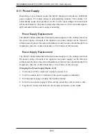
6-11 Power Supply
Depending on your chassis model, the SC827 chassis will include two 1620 Watt
power suppies. This power supply is auto-switching capable. This enables it to
automatically sense and operate at a 100v to 240v input voltage. An amber light
will be illuminated on the power supply when the power is off. An illuminated green
light indicates that the power supply is operating.
Power Supply Replacement
The SC827 chassis utilizes two redundant power supplies. In the unlikely event that
the power supply unit needs to be replaced, one power supply can be removed,
without powering down the system. Replacement units can be ordered directly from
Supermicro (See the contact information in the Preface of this manual).
Changing the Power Supply (Figure 6-19)
1. Power down all four nodes and unplug the power cord.
2. Push the release tab (on the back of the power supply) as illustrated.
3. Pull the power supply out using the handle provided.
4. Push the new power supply module into the power bay until you hear a click.
5. Plug the AC power cord back into the module and power up the nodes.
Summary of Contents for SUPERSERVER 6027TR-H70RF+
Page 1: ... SUPER SUPERSERVER Revision 1 0 SUPERSERVER 6027TR HTRF 6027TR H70RF 6027TR H71RF ...
Page 5: ...v Notes Preface ...
Page 10: ...x Notes SUPERSERVER 6027TR HTRF H70RF H71RF User s Manual ...
Page 28: ...2 10 SUPERSERVER 6027TR HTRF H70RF H71RF User s Manual Notes ...
Page 32: ...SUPERSERVER 6027TR HTRF H70RF H71RF User s Manual 3 4 Notes ...
Page 52: ...4 20 SUPERSERVER 6027TR HTRF H70RF H71RF User s Manual Notes ...
Page 80: ...5 28 SUPERSERVER 6027TR HTRF H70RF H71RF User s Manual Notes ...
Page 87: ...Chapter 6 Advanced Chassis Setup 6 7 Figure 6 5 Replacing a System Fan in the Fan Housing ...
Page 101: ...Chapter 6 Advanced Chassis Setup 6 21 Release Tab Figure 6 19 Changing the Power Supply ...
Page 102: ...6 22 SUPERSERVER 6027TR HTRF H70RF H71RF User s Manual Notes ...
Page 136: ...7 34 SUPERSERVER 6027TR HTRF H70RF H71RF User s Manual Notes ...
Page 138: ...A 2 SUPERSERVER 6027TR HTRF H70RF H71RF User s Manual Notes ...


