6-12
SUPERSERVER 6027TR-HTRF+/H70RF+/H71RF+ User's Manual
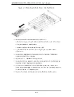
3. Remove the add-on card brackets (see Figure 6-12):
a. Remove screw securing the add-on card bracket to the back of the drawer.
b. Lift the bracket out of the drawer.
c. Repeat this process for the second riser card.
4. Lay the fi rst motherboard in the drawer aligning the standoffs with the
motherboard.
5. Secure the motherboard to the drawer using the rounded, Phillips head
screws included for this purpose.
6. Repeat steps 3 - 5 for the remaining drawers.
7. Secure the CPU(s), heatsinks, and other components to the motherboard as
described in the motherboard documentation.
8. Connect the cables between the motherboard, backplane, chassis, front
panel, and power supply, as needed. Also, fans may be temporarily removed
to allow access to the backplane ports.
9. Replace the add-on card bracket and secure the bracket with a screw.
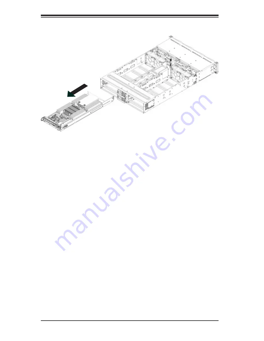
Figure 6-11. Removing the Node Drawer from the Chassis
Summary of Contents for SUPERSERVER 6027TR-H70RF+
Page 1: ... SUPER SUPERSERVER Revision 1 0 SUPERSERVER 6027TR HTRF 6027TR H70RF 6027TR H71RF ...
Page 5: ...v Notes Preface ...
Page 10: ...x Notes SUPERSERVER 6027TR HTRF H70RF H71RF User s Manual ...
Page 28: ...2 10 SUPERSERVER 6027TR HTRF H70RF H71RF User s Manual Notes ...
Page 32: ...SUPERSERVER 6027TR HTRF H70RF H71RF User s Manual 3 4 Notes ...
Page 52: ...4 20 SUPERSERVER 6027TR HTRF H70RF H71RF User s Manual Notes ...
Page 80: ...5 28 SUPERSERVER 6027TR HTRF H70RF H71RF User s Manual Notes ...
Page 87: ...Chapter 6 Advanced Chassis Setup 6 7 Figure 6 5 Replacing a System Fan in the Fan Housing ...
Page 101: ...Chapter 6 Advanced Chassis Setup 6 21 Release Tab Figure 6 19 Changing the Power Supply ...
Page 102: ...6 22 SUPERSERVER 6027TR HTRF H70RF H71RF User s Manual Notes ...
Page 136: ...7 34 SUPERSERVER 6027TR HTRF H70RF H71RF User s Manual Notes ...
Page 138: ...A 2 SUPERSERVER 6027TR HTRF H70RF H71RF User s Manual Notes ...


