background image

5-14

S

UPER

S

ERVER 5017P-TLN4F/TF User's Manual

5-9  Jumper Settings

Explanation of Jumpers

To modify the operation of the mother-
board, jumpers can be used to choose 
between optional settings.  Jumpers 
create shorts between two pins to 
change the function of the connector. 

Pin 1 is identified with a square solder 

pad on the printed circuit board.  See 
the motherboard layout pages for 
jumper locations.

Note:

 On a two-pin jumper, "Closed" 

means the jumper is on both pins and 
"Open" means the jumper is either on 
only one pin or completely removed.

Connector

Pins

Jumper

Setting

3      2      1

3      2      1

CMOS Clear

JBT1 is used to clear CMOS (which will also clear any passwords).  Instead of pins, 
this jumper consists of contact pads to prevent accidentally clearing the contents 
of CMOS.

To clear CMOS, 

1.  First power down the system and unplug the power cord(s).

2.  With the power disconnected, short the CMOS pads with a metal object such 

as a small screwdriver.

3.  Remove the screwdriver (or shorting device).

4.  Reconnect the power cord(s) and power on the system.

Note:


Do not use the PW_ON connector to clear CMOS.

BIOS Write Protect (JWP1)

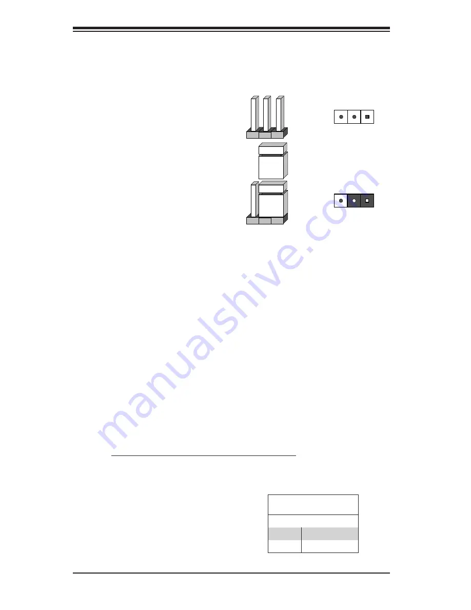
The BIOS Write-Protect jumper (JWP1) 

is used to protect the BIOS firmware from 

accidentally being erased. Close pins 2-3 

before reprogramming the firmware. Oth

-

erwise, this jumper should be enabled 
(pins 1-2) during normal operation.

BMC IPMI Enable/Disable 

Jumper Settings 

Setting     Definition     

Pins 1-2

Enabled (Default)

Pins 2-3

Disabled

Summary of Contents for SUPERSERVER 5017P-TF

Page 1: ...SUPERSERVER 5017P TLN4F 5017P TF SUPER USER S MANUAL 1 0...

Page 2: ...any such disputes Super Micro s total liability for all claims will not exceed the price paid for the hardware product FCC Statement This equipment has been tested and found to comply with the limits...

Page 3: ...0ME serverboard and the SC504 203B chassis Chapter 2 Server Installation This chapter describes the steps necessary to install the SuperServer 5017P TL N4F TF into a rack and check out the server conf...

Page 4: ...guring the serverboard Chapter 6 Advanced Chassis Setup Refer to Chapter 6 for detailed information on the SC504 203B server chassis You should follow the procedures given in this chapter when install...

Page 5: ...Notes Preface v...

Page 6: ...2 1 2 3 Preparing for Setup 2 1 Choosing a Setup Location 2 1 Rack Precautions 2 2 Server Precautions 2 2 Rack Mounting Considerations 2 3 Ambient Operating Temperature 2 3 Reduced Airflow 2 3 Mechan...

Page 7: ...cting Power Cables 5 2 Connecting the Control Panel 5 2 5 3 Rear I O Ports 5 3 5 4 Onboard Processor and Heatsink 5 4 5 5 Installing Memory 5 4 How to Install SO DIMMs 5 4 Memory Support 5 4 5 6 Addin...

Page 8: ...lacing the Power Supply 6 8 Chapter 7 BIOS 7 1 Introduction 7 1 Starting BIOS Setup Utility 7 1 How To Change the Configuration Data 7 1 How to Start the Setup Utility 7 2 7 2 Main Setup 7 2 7 3 Advan...

Page 9: ...rmation on operating systems that have been certified for use with the system www supermicro com In addition to the motherboard and chassis various hardware components have been included with the 5017...

Page 10: ...sors www supermicro com Memory The X9SPV LN4F F 3610ME has two SO DIMM slots that can support up to 16 GB of unbuffered DDR3 1333 1066 800 memory See Chapter 5 for details Serial ATA A SATA controller...

Page 11: ...moved from the system and the AC power cord removed when replacing See Chapter 6 for details Hard Drive Subsystem Either two 3 5 internal drive or four 2 5 internal drives with a 2 5 HDD bracket are s...

Page 12: ...SVID PCIe x16 SLOT RJ45 RJ45 ECC SODIMM2 ECC SODIMM1 DDR3 CHB 1333 1067 MHz 8 0GT s 5 0GT s DMI 2 0 x4 2x SATA PORTS USB2 0 SATA 6Gb s PCIe1 0_x1 2 5GT s GLAN1 82574L Debug Header x2 TWO PORT HEADERs...

Page 13: ...per Micro Computer B V Het Sterrenbeeld 28 5215 ML s Hertogenbosch The Netherlands Tel 31 0 73 6400390 Fax 31 0 73 6416525 Email sales supermicro nl General Information support supermicro nl Technical...

Page 14: ...1 6 SUPERSERVER 5017P TLN4F TF User s Manual Notes...

Page 15: ...a suitable location for the rack unit that will hold the SuperServer 5017P TLN4F TF It should be situated in a clean dust free area that is well ventilated Avoid areas where heat electrical noise and...

Page 16: ...her Always make sure the rack is stable before extending a component from the rack You should extend only one component at a time extending two or more si multaneously may cause the rack to become uns...

Page 17: ...omised Mechanical Loading Equipment should be mounted into a rack so that a hazardous condition does not arise due to uneven mechanical loading Circuit Overloading Consideration should be given to the...

Page 18: ...hould also refer to the installation instructions that came with the rack unit you are using Installing the Chassis into a Standard Rack 1 Confirm that chassis includes the four mounting screws requir...

Page 19: ...ur total 2 First determine how far follow the server will extend out the front of the rack Larger chassis should be positioned to balance the weight between front and back 3 If a bezel is included on...

Page 20: ...2 6 SUPERSERVER 5017P TLN4F TF User s Manual Notes...

Page 21: ...specific components There are also two buttons on the chassis control panel 3 2 Control Panel Buttons There are two buttons located on the front of the chassis a reset button and a power on off butto...

Page 22: ...1 2 3 3 Control Panel LEDs The control panel located on the front of the chassis has five LEDs These LEDs provide you with critical information related to different parts of the system This section ex...

Page 23: ...hen illuminated the green LED on the SATA drive carrier indicates drive activity A connection to the SATA backplane enables this LED to blink on and off when that particular drive is being accessed Pl...

Page 24: ...SUPERSERVER 5017P TLN4F TF User s Manual 3 4 Notes...

Page 25: ...you should first power down the system with the operating system first and then unplug the power cords of all the power supply units in the system When working around exposed electrical circuits anoth...

Page 26: ...our body which are excellent metal conductors that can create short circuits and harm you if they come into contact with printed circuit boards or areas where power is present Serverboard Battery CAUT...

Page 27: ...use Touch a grounded metal object before removing the board from the antistatic bag Do not let components or PCBs come into contact with your clothing which may retain a charge even if you are wearing...

Page 28: ...strictly followed Figure 4 1 Installing the Onboard Battery LITHIUM BATTERY BATTERY HOLDER BATTERY HOLDER LITHIUM BATTERY OR Please handle used batteries carefully Do not damage the battery in any way...

Page 29: ...e hand under the center of the board to support it when handling The following measures are generally sufficient to protect your equipment from electric static discharge Precautions Use a grounded wri...

Page 30: ...ted should be connected See the layout on page 5 10 for connector locations SATA drive data cables I SATA1 I SATA3 Control Panel cable JF1 Important Make sure the the cables do not come into contact w...

Page 31: ...ports Figure 5 2 Rear I O Ports Rear I O Ports 1 COM Port 1 7 PS 2 Keyboard Mouse 2 USB Port 5 8 Gb LAN Port 2 3 USB Port 4 9 Gb LAN Port 1 4 Dedicated IPMI LAN Port 10 Gb LAN Port 4 X9SPV LN4F only...

Page 32: ...nstallation 2 Insert each SO DIMM module vertically and snap it into place Repeat step 1 to install DIMMB1 if needed See instructions on the next page Memory Support The X9SPV LN4F F 3610ME motherboar...

Page 33: ...ould release it from the slot Pull the SO DIMM module upwards The SO DIMM Socket Position the SO DIMM module s bottom key so it aligns with the receptive point on the slot Take note of the module s si...

Page 34: ...M1 JDIMM2 JCOM1 FAN2 FAN3 FAN1 FAN4 U26 JPW1 JPI2C1 JPK1 U3 JTPM1 JLAN1 JLAN2 MH7 MH6 MH2 MH4 JD1 JF1 JP1 JPUSB1 JPB1 JWP1 JL1 JOH1 MH4 U57 X9SPV F JTPM1 TPM PORT80 DOM POWER P1 DIMMB1 USB8 9 IPMI JSD...

Page 35: ...kpanel USB Ports FAN1 4 CPU Fan System Fan and Auxilliary Fan Headers T SGPIO1 T SGPIO2 Serial General Purpose I O Headers JPI2C1 JPI2C PWR supply I2C System Management Bus JF1 Front Panel Control Hea...

Page 36: ...COM 16 PS_ON 4 5V 17 COM 5 COM 18 COM 6 5V 19 COM 7 COM 20 Res NC 8 PWR_OK 21 5V 9 5VSB 22 5V 10 12V 23 5V 11 12V 24 COM 12 3 3V Reset Button Pin Definitions JF1 Pin Definition 3 Reset 4 Ground Power...

Page 37: ...le on the right for pin definitions NIC1 LED Pin Definitions JF1 Pin Definition 11 Vcc 12 Ground NIC1 LED The LED connections for LAN1 are on pins 11 and 12 of JF1 Attach an LED cable to display netwo...

Page 38: ...n header is des ignated JL1 Attach a chassis intrusion cable from the chassis to inform you of a chassis intrusion when the chassis is opened Chassis Intrusion Pin Definitions Pin Definition 1 Intrusi...

Page 39: ...n 1 5V 6 5V 2 USB_PN 7 USB_PN 3 USB_PP 8 USB_PP 4 Ground 9 Ground 5 NA 10 Key LAN Ports LAN1 LAN4 Two gigabit LAN ports are located on the I O back panel four on the X9SPV LN4F These ports accept RJ45...

Page 40: ...n external speaker If you wish to use the onboard speaker please close pins 6 7 See the table on the right for speaker pin definitions Speaker Connector Pin Settings Pin Setting Definition Pins 4 7 Ex...

Page 41: ...C Header The power System Management Bus header at JPI2 C2 is used to monitor the status of the power supply fan and system temperature See the table on the right for pin definitions PWR SMB Pin Defi...

Page 42: ...S which will also clear any passwords Instead of pins this jumper consists of contact pads to prevent accidentally clearing the contents of CMOS To clear CMOS 1 First power down the system and unplug...

Page 43: ...signal for the application that hangs See the table on the right for jumper settings Watch Dog must also be enabled in BIOS Watch Dog Jumper Settings Setting Definition Pins 1 2 Reset Pins 2 3 NMI Op...

Page 44: ...ower cable is connected and the power supply hard switch is on The system may be on standby or running Onboard PWR LED LED1 LED Status Status Definition Off System Off Soft Switch On Power is Detected...

Page 45: ...3 TXN 4 Ground 5 RXN 6 RXP 7 Ground Serial ATA Ports Two Serial ATA SATA 3 0 connec tors I SATA 0 1 are located on the motherboard In addition four SATA 2 0 I SATA 2 5 connectors are also located on t...

Page 46: ...aged with your motherboard Driver Tool Installation Display Screen Note Click the icons showing a hand writing on paper to view the readme files for each item Click the computer icons to the right of...

Page 47: ...ment and operations of your system SuperDoctor III displays crucial system information such as CPU temperature system voltages and fan status See the Figure below for a display of the SuperDoctor III...

Page 48: ...II Interface Display Screen Remote Control Note The SuperDoctor III program and User s Manual can be downloaded from the Supermicro web site at http www supermicro com products accessories software Su...

Page 49: ...Chapter 5 Advanced Motherboard Setup 5 21...

Page 50: ...very carefully The following measures are generally sufficient to protect your equipment from ESD damage Precautions Use a grounded wrist strap designed to prevent static discharge Touch a grounded me...

Page 51: ...bundled these wires together to simplify the connection Connect the cable from JF1 on the serverboard to the Control Panel PCB printed circuit board Make sure the red wire plugs into pin 1 on both con...

Page 52: ...he chassis cover in place There are two screws on each side of the chassis and one screw on the back 3 Once the screws have been removed lift the cover upward to remove it from the chassis Caution Exc...

Page 53: ...n the mounting holes in the single fan housing with the holes in the floor of the chassis 6 Secure the single fan housing to the floor of the chassis 7 Connect the fan cables to the motherboard and pu...

Page 54: ...e 6 6 for supported configuration options 3 Place the hard drive and bracket into the chassis as illustrated in Figure 6 3 If up to four 2 5 hard drives are desired rotate the hard drive brackets nine...

Page 55: ...n Card One 3 5 Hard Drive and one Low Profile Expansion Card Two 2 5 Hard Drives and One Full Height Half Length Expansion Card Hard Drive Configuration Options 2 5 and 3 5 hard drives are supported i...

Page 56: ...p on the back of the chassis 2 Remove the screws holding the expansion card clip and the PCI slot cover which covers the PCI slot opening in the back of the chassis 3 Remove the expansion card clip an...

Page 57: ...the riser card 5 Simultaneously insert the PCI slot bracket of the expansion card into the open PCI slot and insert the riser card in to the riser card slot on the motherboard 6 Replace the expansion...

Page 58: ...ace Replacing the Power Supply Replacing the Power Supply 1 Power down the system disconnect the power cord and remove the chassis cover 2 Disconnect all wiring from the power supply 3 Remove the four...

Page 59: ...Align the mounting thru holes on the power supply with the mounting holes in the chassis and reattach the power supply to the chassis using the four screws which were previously set aside 6 Reconnect...

Page 60: ...displays all the options that can be configured Grayed out options cannot be configured Options in blue can be configured by the user The right frame displays the key legend Above the key legend is an...

Page 61: ...Do not upgrade the BIOS unless your system has a BIOS related issue Flashing the wrong BIOS can cause irreparable damage to the system In no event shall Supermicro be liable for direct indirect specia...

Page 62: ...between fields The date must be entered in Day MM DD YY format The time is entered in HH MM SS format Note The time is in the 24 hour format For example 5 30 P M appears as 17 30 00 Supermicro X9SPV...

Page 63: ...ns to be modified between POST mes sages or the OEM logo Select Disabled to display the POST messages Select Enabled to display the OEM logo instead of the normal POST messages The op tions are Enable...

Page 64: ...stem turns off Select Instant Off if you want the system to instantly power off when the Power Button is pressed The options are 4 Seconds Override and Instant Off Restore on AC Power Loss Use this fe...

Page 65: ...the feature of Virtualization Technology to allow one plat form to run multiple operating systems and applications in independent partitions creating multiple virtual systems in one physical computer...

Page 66: ...Report This BIOS feature enables or disables C3 ACPI C2 and C6 ACPI C3 reporting to the operating system The options are Disabled and Enabled Config TDP LOCK Use this feature to lock the Config TDP Co...

Page 67: ...t Time Enter the amount of time in nano seconds to wait for switch DDR voltage The minimum value is 20ns The default value is 2000000 ECC Support Select Enabled to support ECC The options are Enabled...

Page 68: ...t ing IGFX PEG will enable the Intel HD 4000 GPU PCH IO Configuration This submenu allows you to configure PCH Parameters USB Configuration Legacy USB Support This feature enables support for legacy U...

Page 69: ...to Disabled the specified port is routed to EHCI The options are Enabled and Disabled Note If HS port is routed to xHCI the corresponding SS port is enabled XHCI Streams Use this feature to enable the...

Page 70: ...de and RAID Mode The following are displayed depending on your selection IDE Mode The following items are displayed when IDE Mode is selected Serial ATA Port 0 5 This item displays the information det...

Page 71: ...acy only Other PCI device ROM priority This feature specifies what ROM to launch for PCI devices other than network mass storage or video The options are UEFI OpROM and Legacy OpROM PCI Latency Timer...

Page 72: ...s video add on cards to borrow the color palette from the system s video card The options are Enabled and Disabled PCI Express Settings Relaxed Ordering Select Enabled to allow certain PCI E transacti...

Page 73: ...many microseconds a software pro gram should wait before polling the Link Training bit in the Link Status Register The range is between 10 to 1000 The default setting is 500 Unpopulated Links Select...

Page 74: ...number of ID Based Or dering IDO bit Attribute 2 requests to be initiated The options are Disabled and Enabled LTR Mechanism Enable Available when supported by the hardware When set to Enabled this fe...

Page 75: ...orrecting unstable link operation The options are Enabled and Disabled PCI E Slot 1 Option ROM Use this feature to enable or disable PCI E slot 1 Option ROM The options are Disabled and Enabled Onboar...

Page 76: ...Port 1 Settings Serial Port 2 Settings This option specifies the base I O port address and the Interrupt Request address of Serial Port 1 and Serial Port 2 Select Disabled to prevent the serial port...

Page 77: ...for a serial port used in Console Redirec tion Make sure that the same speed is used in the host computer and the client computer A lower transmission speed may be required for long and busy lines The...

Page 78: ...The options are Dis abled and Enabled Legacy OS Redirection Resolution Use this feature to select the number of rows and columns used in Console Redirection for legacy OS support The options are 80x2...

Page 79: ...nt computer A lower transmission speed may be required for long and busy lines The options are 9600 19200 57600 and 115200 bits per second Flow Control This feature allows the user to set the flow con...

Page 80: ...protocol and the INT1A interface will not be available Intel TXT LT Configuration Secure Mode Extensions SMX This feature can be configured if it is supported by the processor Enable this feature to...

Page 81: ...nabled to allow a DHCP server to assign the IP addresses for this attempt If this is set to Disabled then you need to enter the Initiator IP Address Subnet Mask and Gateway manually Target Name Enter...

Page 82: ...s Half 10 Mbps Full 100 Mbps Half and 100 Mbps Full Wake On LAN Use this feature to activate the Wake On LAN WOL feature The options are Enabled and Disabled Blink LEDs Range 0 15 seconds Please speci...

Page 83: ...hen it is full The options are Do Nothing and Erase Immediately Log System Boot Event This option toggles the System Boot Event logging to enabled or disabled The options are Disabled and Enabled MECI...

Page 84: ...Log This feature is used to change the System Event Log SEL configuration SEL Components Change this item to enable or disable all features of System Event Logging The options are Enabled and Disabled...

Page 85: ...namic Host and Configuration Protocol server or manually entered by the user Static When DHCP is selected all the options below are automatically assigned to the system by itself or by an external DHC...

Page 86: ...ify which devices are boot devices and the order of priority from which the system boots during startup Boot Option 1 Boot option 2 Boot Option 3 etc The settings are any detected boot device and Disa...

Page 87: ...ed during each system startup or boot and will also have Administrator rights in the setup Passwords must be at least 3 and up to 20 characters long Administrator Password Press Enter to create a new...

Page 88: ...ter Select Discard Changes and Exit from the Exit menu and press Enter Save Changes and Reset When you have completed the system configuration changes select this option to leave the BIOS Setup Utilit...

Page 89: ...tore User Defaults from the Exit menu and press En ter Use this feature to retrieve user defined settings that were saved previously Boot Override Listed on this section are other boot options for the...

Page 90: ...s Recoverable POST Error Beep Codes When a recoverable type of error occurs during POST BIOS will display a POST code that describes the problem BIOS may also issue one of the following beep codes 1 l...

Page 91: ...A 2 SUPERSERVER 5017P TLN4F TF User s Manual Notes...

Page 92: ...IOS 16 MB AMI SPI Flash ROM Memory Capacity Two SO DIMM slots that can support up to 16 GB of unbuffered DDR3 1333 1066 800 memory Note see Section 5 6 for details Drive Bays Two 3 5 internal drives o...

Page 93: ...dity 8 to 90 non condensing Non operating Relative Humidity 5 to 95 non condensing Regulatory Compliance Electromagnetic Emissions FCC Class A EN 55022 Class A EN 61000 3 2 3 3 CISPR 22 Class A Electr...

Page 94: ...B 1 Appendix B System Specifications Notes...

Page 95: ...perform be reasonably expected to result in significant injury or loss of life or catastrophic property damage Accordingly Supermicro dis claims any and all liability and should buyer use or sell such...

Reviews: