Chapter 2: Installation
2-7
S
U
P
E
R
P
D
S
M
i-
L
N
4
®
JF1 Header Pins
To Remove:
Use your thumbs to
gently push each
release tab outward
to release the DIMM
from the slot.
Top View Of DDR 2 Slot
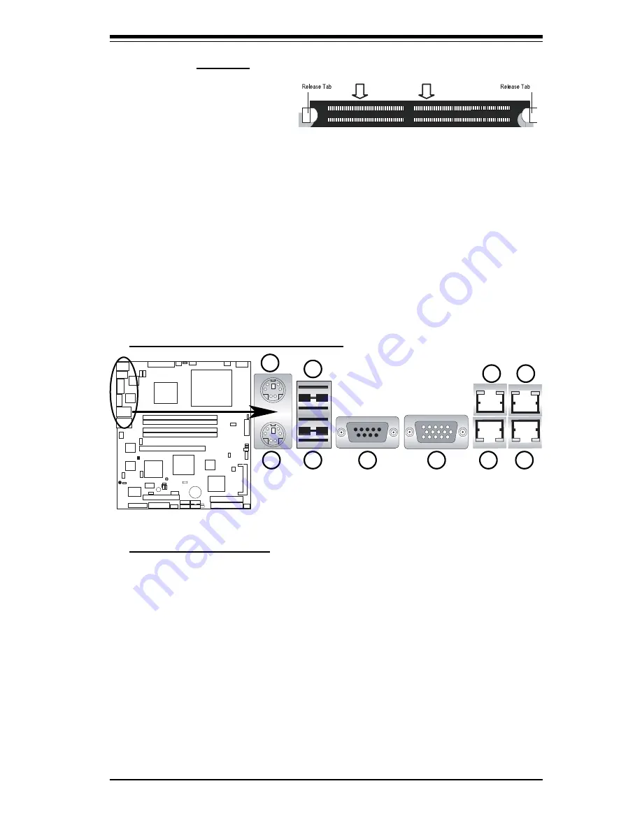
2-5 Control Panel Connectors/IO Ports
The I/O ports are color coded in conformance with the PC 99 specifi cation. See
the fi gure below for the colors and locations of the various I/O ports.
A. Back Panel Connectors/IO Ports
Back Panel I/O Port Locations and Defi nitions
Back Panel Connectors
Keyboard (Purple)
1.
PS/2 Mouse (Green)
2.
Back Panel USB Port 1
3.
Back Panel USB Port 2
4.
COM Port 1 (Turquoise)
5.
VGA Port (Blue)
6.
Gigabit LAN 2
7.
Gigabit LAN 1
8.
Gigabit LAN 4
9.
Gigabit LAN 3
10.
(*See Section 2-6 for details.)
1
2
3
4
5
6
7
8
9
10
Note to Microsoft® Windows® Users:
Microsoft implemented a design change in
Windows XP with Service Pack 2 (SP2) and Windows Vista. This change is specifi c to
the Physical Address Extension (PAE) mode behavior which improves driver compat-
ibility. For more information, please read the following article at Microsoft’s Knowledge
Base website at: http://support.microsoft.com/kb/888137.


