


5-16
A+ SERVER 4042G-6RF/TRF User's Manual
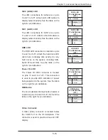
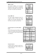
JIBTN1 Header
A RAIDKey header, located at JIBTN1,
provides RAID function support in order to
use RAID 5 SAS support. This connector is
only available on the H8QG6-F serverboard,
LAN1/2 (Ethernet Ports)
Two Gigabit Ethernet ports (designated
LAN1 and LAN2) are located beside the
VGA port. Additionally, there is a dedicated
LAN port for IPMI on top of the two rear USB
ports. These Ethernet ports accept RJ45
type cables.
LAN Ports (LAN1/2)
Pin Definition
Pin# Definition Pin# Definition
1
P2V5SB
10
SGND
2
TD0+
11
Act LED
3
TD0-
12
P3V3SB
4
TD1+
13
Link 100 LED
(Yellow, +3V3SB)
5
TD1-
14
Link 1000 LED
(Yellow, +3V3SB)
6
TD2+
15
Ground
7
TD2-
16
Ground
8
TD3+
17
Ground
9
TD3-
18
Ground
Note:
NC indicates no connection.
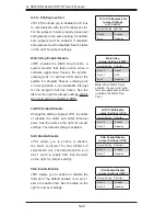
Universal Serial Bus Ports
Two Universal Serial Bus ports (USB 2.0) are
located beside the Keyboard and Mouse PS2
ports. One additional Type A port (USB6) is
also included on the motherboard. See the
table on the right for pin definitions.
Universal Serial Bus Ports
Pin Definitions (USB 0/1,
USB6)
USB0/1
Pin # Definition
USB6
Pin # Definition
1
+5V
1
+5V
2
PO-
2
PO-
3
PO+
3
PO+
4
Ground
4
Ground
USB Headers
Four USB 2.0 headers (USB2/3 and USB4/5)
are also included on the motherboard.
These may be connected to provide front
side access. A USB cable (not included) is
needed for the connection. See the table on
the right for pin definitions.
Universal Serial Bus Headers
Pin Definitions
(USB2/3, USB4/5)
JUSB2, JUSB3
Pin # Definition
Pin # Definition
1
+5V
2
+5V
3
PO-
4
PO-
5
PO+
6
PO+
7
Ground
8
Ground
9
Key
10
NC
Note:
NC indicates no connection.
Summary of Contents for A+ SERVER 4042G-6RF
Page 1: ... SUPER A SERVER 4042G 6RF TRF USER S MANUAL Revision 1 0d ...
Page 5: ...v Preface Notes ...
Page 10: ...Notes x A SERVER 4042G 6RF TRF User s Manual ...
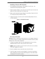
Page 25: ...Chapter 2 Server Installation 2 9 Figure 2 5 Accessing the Inside of the System ...
Page 30: ...3 4 4042G 6RF TRF User s Manual Notes ...
Page 50: ...4 20 A SERVER 8027R TRF 7RFT User s Manual Notes ...
Page 92: ...6 10 A SERVER 4042G 6RF TRF User s Manual Figure 6 7 Removing a Power Supply Module ...
Page 110: ...A 2 A SERVER 4042G 6RF TRF User s Manual Notes ...