


6-2
S
UPER
S
TORAGE
S
YSTEM 2027R-AR24 User's Manual
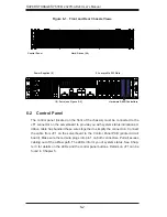
Figure 6-1. Front and Rear Chassis Views
6-2 Control
Panel
The control panel (located on the front of the chassis) must be connected to the
JF1 connector on the serverboard to provide you with system status indications. A
ribbon cable has bundled these wires together to simplify the connection. Connect
the cable from JF1 on the serverboard to the Control Panel PCB (printed circuit
board). Make sure the red wire plugs into pin 1 on both connectors. Pull all excess
cabling out of the air
fl
ow path. The LEDs inform you of system status. See Chap-
ter 3 for details on the LEDs and the control panel buttons. Details on JF1 can be
found in Chapter 5.
Hard Drives (24)
Control Panel
I/O Ports (see Figure 5-2)
Power Supplies (2)
5 Low-profi le PCI Slots
Hardware RAID Controllers
Summary of Contents for 2027R-AR24
Page 1: ...SUPER STORAGE SYSTEM 2027R AR24 SUPER USER S MANUAL 1 0...
Page 5: ...Notes Preface v...
Page 24: ...2 10 SUPERSTORAGESYSTEM 2027R AR24 User s Manual Notes...
Page 28: ...3 4 SUPERSTORAGESYSTEM 2027R AR24 User s Manual Notes...
Page 48: ...4 20 SUPERSTORAGESYSTEM 2027R AR24 User s Manual Notes...
Page 90: ...6 12 SUPERSTORAGESYSTEM 2027R AR24 User s Manual Notes...
Page 122: ...A 2 SUPERSTORAGESYSTEM 2027R AR24 User s Manual Notes...


