


Chapter 5: Advanced Serverboard Setup
5-17
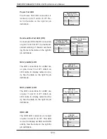
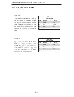
Reset Button
The Reset Button connection is
located on pins 3 and 4 of JF1 and
attaches to the reset switch on the
computer chassis. See the table on
the right for pin de
fi
nitions.
Power Button
The Power On connection is on pins
1 and 2 of JF1. These should be
connected to the chassis power but-
ton. See the table on the right for pin
de
fi
nitions.
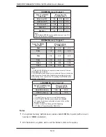
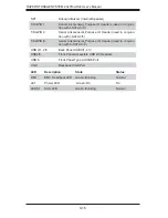
5-8 Connector
Defi nitions
Required Connection
ATX Power 24-pin Connector
Pin Defi nitions
Pin# De
fi
nition Pin # De
fi
nition
13
+3.3V
1
+3.3V
14
-12V
2
+3.3V
15
COM
3
COM
16
PS_ON
4
+5V
17
COM
5
COM
18
COM
6
+5V
19
COM
7
COM
20
Res (NC)
8
PWR_OK
21
+5V
9
5VSB
22
+5V
10
+12V
23
+5V
11
+12V
24
COM
12
+3.3V
Reset Button
Pin Defi nitions (JF1)
Pin# De
fi
nition
3
Reset
4
Ground
Power Button
Pin Defi nitions (JF1)
Pin# De
fi
nition
1
Power Signal
2
Ground
Secondary Power Connector
JPWR1 and JPWR2 must also be
connected to the power supply. See
the table on the right for pin de
fi
ni-
tions.
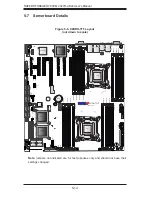
Power Connectors
A 2 4 - p i n m a i n p o w e r s u p p l y
connector(J22) and two 8-pin power
connectors (JPWR1/JPWR2) are
provided on the serverboard. These
power connectors meet the SSI EPS
12V speci
fi
cation. These power con-
nectors must be connected to your
power supply. See the table on the
right for pin de
fi
nitions.
+12V 8-pin Power
Pin Defi nitions
Pins De
fi
nition
1 - 4
Ground
5 - 8
+12V
Summary of Contents for 2027R-AR24
Page 1: ...SUPER STORAGE SYSTEM 2027R AR24 SUPER USER S MANUAL 1 0...
Page 5: ...Notes Preface v...
Page 24: ...2 10 SUPERSTORAGESYSTEM 2027R AR24 User s Manual Notes...
Page 28: ...3 4 SUPERSTORAGESYSTEM 2027R AR24 User s Manual Notes...
Page 48: ...4 20 SUPERSTORAGESYSTEM 2027R AR24 User s Manual Notes...
Page 90: ...6 12 SUPERSTORAGESYSTEM 2027R AR24 User s Manual Notes...
Page 122: ...A 2 SUPERSTORAGESYSTEM 2027R AR24 User s Manual Notes...


