


Chapter 2: Installation
2-5
A
IPMI CODE
C A
BIOS
LICENSE
BAR CODE
MAC CODE
C
A
A
C
A
C
A
+
JLAN3
JLAN2
JLAN1
JP1000
JPW
1
JPW2
JSTBY1
J4
LE6
DIMM1 DIMM2
DIMM4
DIMM3
FAN4
FA
N3
FAN2 FAN1
FANA
JPME1
JI2C1
JPME2
JI2C2
JPUSB1
JPL1
JPL2
JPL3
JPG
1
JBR
1
JWD1
JLED
1
LE5
LE
4
LE1
LE
3
J3
JL
1
JLED_LAN
4
JLED_LAN
3
JLED_LAN6
JLED_LAN
5
JPI2C1
JTPM1
T-SGPIO1
T-SGPIO2
JSD2
JSD1
SPKR1
B1
JBT1
JF
1
SW
1
COM1
COM2
PCH SLOT4 PCI-E 2.0 X4(IN X8
)
DESIGNED IN USA
X10SLH-LN6TF
REV:1.01
USB0(3.0)
USB1(3.0)
USB12/13
USB8/9
CPU SLOT6 PCI-E 3.0 X8(IN X16)
I-SA
TA
0
I-SA
TA
2
I-SA
TA
1
I-SA
TA
3
I-SA
TA
4
I-SA
TA
5
VGA
LAN5/6
LAN3/4
LAN1/2
USB4/5 (2.0)
USB2/3(3.0)
JLED1:3 pin Power LED
IPMI LAN
JF
1
NIC2
NIC1
ON
PWR
X
RST
OH/
FF
LED
LED
HDD
X
PWR
NMI
C226
X540
X540
X540
BMC
PLX
Caution:
1) To avoid damaging the motherboard and its components, please do
not use a force greater than 8 lb/inch on each mounting screw during motherboard
installation. 2) Some components are very close to the mounting holes. Please take
precautionary measures to avoid damaging these components when installing the
motherboard to the chassis.
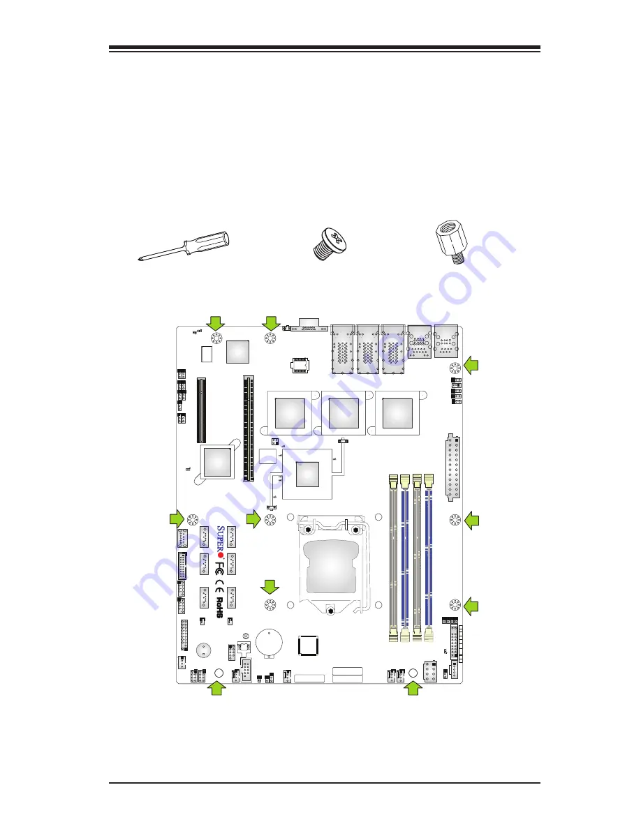
2-3 Motherboard Installation
All motherboards have standard mounting holes to fit different types of chassis.
Make sure that the locations of all the mounting holes for both motherboard and
chassis match. Although a chassis may have both plastic and metal mounting fas-
teners, metal ones are highly recommended because they ground the motherboard
to the chassis. Make sure that the metal standoffs click in or are screwed in tightly.
Then use a screwdriver to secure the motherboard onto the motherboard tray.
Tools Needed
Philips Screwdriver
(1)
Standoffs (10)
Only if Needed
Philips Screws (10)
Location of Mounting Holes


